
Method for preparing ball-shaped bump biological microelectrode array

A technology of micro-electrode arrays and spherical protrusions, which is applied in the direction of optomechanical equipment, chemical instruments and methods, circuits, etc., can solve the problems of increasing the impedance of electrodes and tissues, which is not conducive to the transmission of stimulation signals, and the contact resistance between metals becomes larger. To achieve the effect of improving stimulation effect, improving stimulation effect and reducing impedance

Inactive Publication Date: 2008-03-26
SHANGHAI JIAO TONG UNIV
View PDF0 Cites 30 Cited by
  • Summary
  • Abstract
  • Description
  • Claims
  • Application Information

AI Technical Summary

Problems solved by technology

On the one hand, the cost of the electrodes produced in this way is high, and the contact resistance between the metals is increased by the electroplating method, which increases the impedance between the electrodes and the tissue, which is not conducive to the transmission of stimulation signals.
In addition, because the material is in the electroplating solution for a long time, it will also damage the material itself

Method used


Image

  • Method for preparing ball-shaped bump biological microelectrode array

Examples


Embodiment

[0030] 1. Clean the silicon wafer, and sputter metal chromium (Cr) on the silicon wafer to 800 Ȧ;

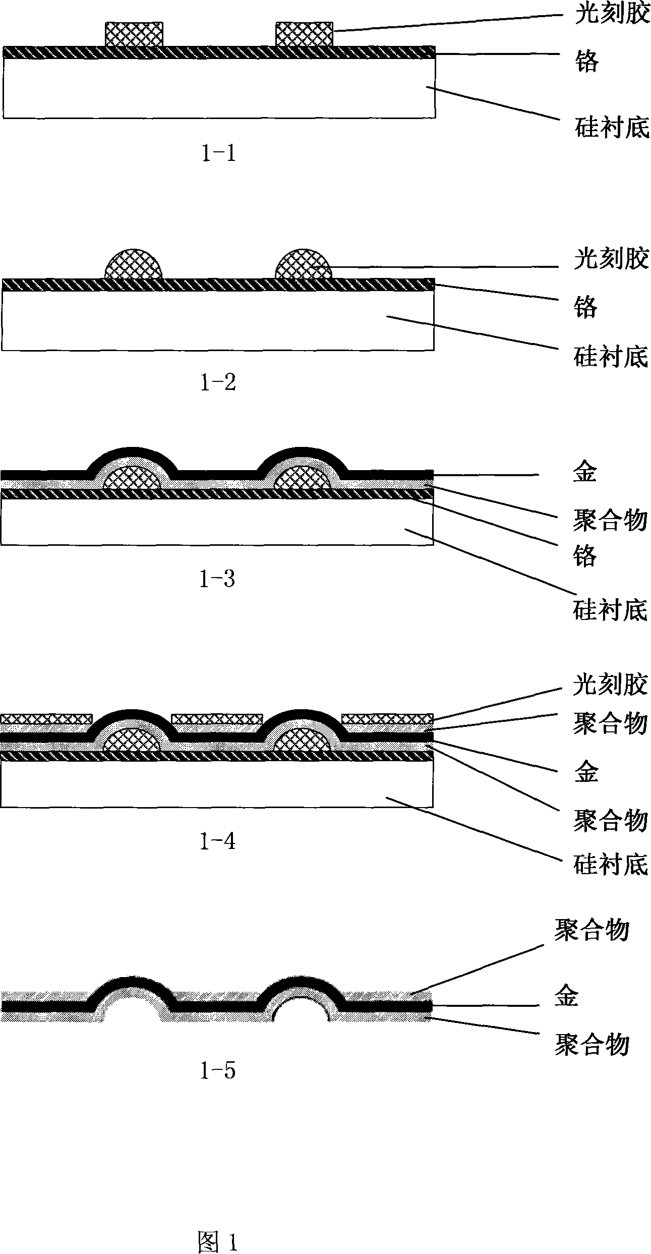
[0031] 2. Spin-coat positive photoresist AZ4903 (1200 rpm, 60 seconds) on the metal surface, expose, remove the photoresist in the exposed area with AZ-400K developer (160 seconds to 200 seconds), and obtain a raised photoresist The small cylinder is 15um, as shown in Figure 1-1;

[0032] 3. Bake the photoresist in an oven at a high temperature at 160C-200C for 20-30 minutes to form a photoresist with a hemispherical structure, as shown in Figure 1-2;

[0033] 4. Deposit the polymer parylene7-8um, as the bottom wrapping material of the microelectrode array;

[0034] 5. Sputter metal gold 0.5um, spin-coat photoresist AZ4903 (3000 rpm, 60 seconds), expose, develop (140 seconds to 160 seconds), pattern the wires and electrode points of the microelectrode array, as shown in Figure 1 -3;

[0035] 6. Deposit the polymer parylene5um as the upper wrapping material of the microelectro...


PUM


Abstract

This invention discloses a sort of method that it uses the light-sensitive lacquer hot-melt method to prepare the roundness heave biologic micro-electrode array. It uses the light-sensitive lacquer technique to prepare the heave cylindrical light-sensitive lacquer, and it adopts the hot-melt circumfluence light-sensitive lacquer to form the roundness salient point. A bed of polymer which is covered in the underlay is used for the protecting material of the bottom of the device, and the presented in figures forms the metal electrode point and the lead, and then that it covers the polymer to be the protecting material of the top of the device. The presented in figures reveals the electrode point and the weld point, and it gets the needed roundness heave smooth micro-electrode array. The cost of the invention is low, also the technical process is simple, and it has the upper irritant effect. It is used for the preparation of the biologic micro-electrode array which has the nerve-cell stimulation of the retina prosthesis and so on.

Description

technical field [0001] The invention relates to a manufacturing method in the technical field of micromachining, in particular to a method for preparing a spherical convex biological microelectrode array by using a photoresist hot-melt method. Background technique [0002] Primary retinitis pigmentosa (RP) and age-related macular degeneration (AMD) are the leading causes of blindness due to the progressive degeneration of the outer layer of the retina. Due to the development of microelectronics and biotechnology, implantable microstimulators can be used to stimulate the retina to produce vision. [0003] In the retinal prosthesis system, the microelectrode array used to stimulate the retina is a very important part, and the performance of the electrodes is directly related to the stimulation effect of the electrical pulse on the nerve cells. At present, electrodes used to stimulate nerve cells such as the retina mainly use high-density micro-electrode arrays processed by ME...

Claims


Application Information

Patent Timeline
Patent Type & Authority Applications(China)
IPC IPC(8): G03F7/00G03F7/26G03F7/039B81C5/00A61F2/14A61F9/007B81C99/00
Inventor 刘景全王亚军杨春生陈迪
Owner SHANGHAI JIAO TONG UNIV
Learn More