Sintering smoke wet method sulphur removing and dust removing technology

A technology for sintering flue gas and wet desulfurization, which is applied in the field of wet desulfurization and dust removal technology, can solve the problems of deterioration of GGH working conditions, complex composition of sintering flue gas, and low dust removal efficiency, so as to improve resource utilization and alleviate chlorine pollution. Corrosion problems, effects of mitigating enrichment effects

Active Publication Date: 2008-04-30
BAOSHAN IRON & STEEL CO LTD +1
View PDF2 Cites 38 Cited by
  • Summary
  • Abstract
  • Description
  • Claims
  • Application Information

AI Technical Summary

Problems solved by technology

However, the gas-liquid mass transfer efficiency of the spray tower is average. To remove such a low concentration of SO 2 , it is necessary to ensure that the spray slurry is fully covered on the section of the absorption tower, and even the coverage between the spray layer and the layer exceeds 200%, so the corresponding liquid-gas ratio (W/G) is relatively large (generally W/G is 12 ~20), the power consumption is very large, and the economy is poor
[0008] (2) Compared with the flue gas of coal-fired boilers, the particle size of dust particles in sintering flue gas is smaller, and the proportion of submicron dust is higher. The dust removal efficiency of traditional spray towers in this particle size range is not high
[0009] (3) The temperature of the sintering flue gas from the electrostatic precipitator is relative

Method used


Image

  • Sintering smoke wet method sulphur removing and dust removing technology
  • Sintering smoke wet method sulphur removing and dust removing technology

Examples


Embodiment Construction

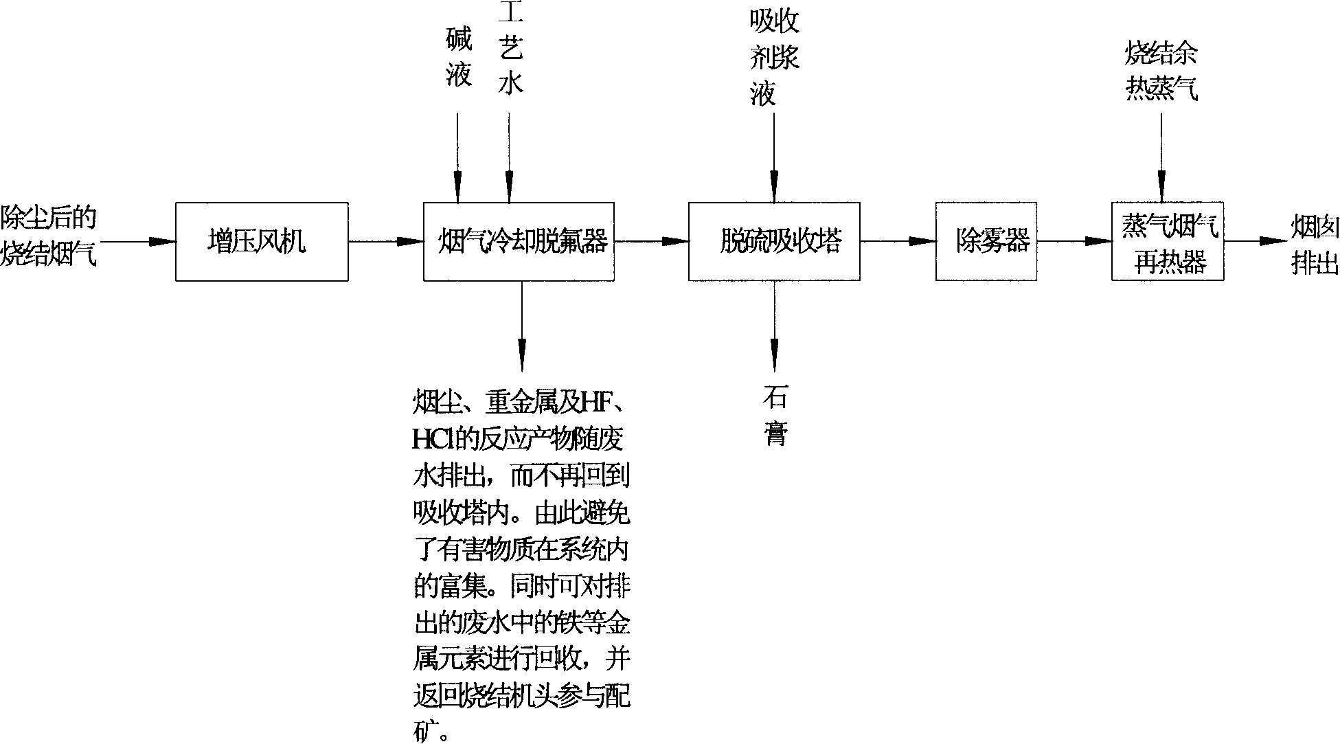
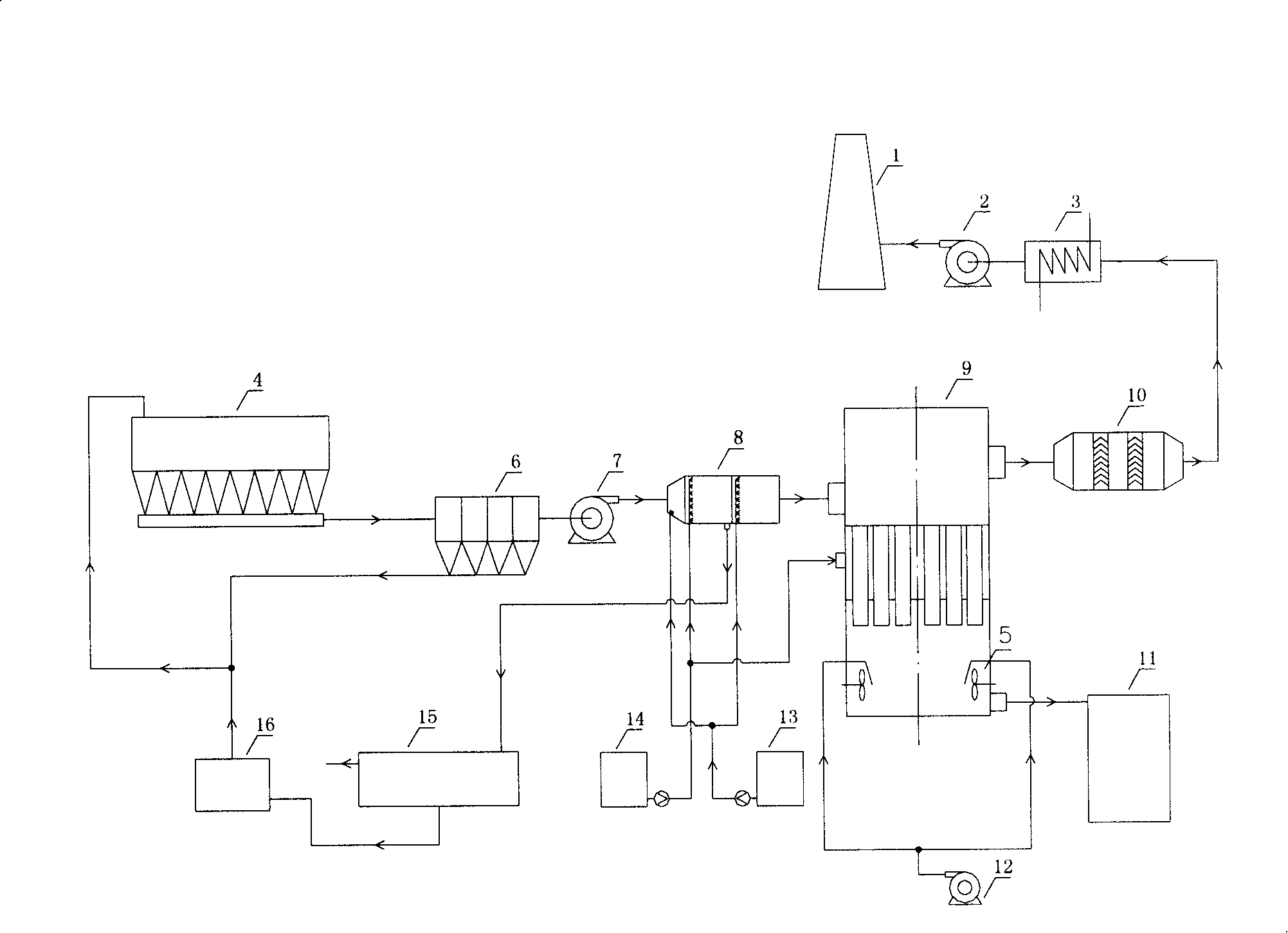
[0040] Depend on Figure 1 to Figure 2 It can be seen that the sintering flue gas to be treated from the electrostatic precipitator 6 is first boosted by the booster fan 7, and then enters the cooling defluorination device 8 located at the front of the desulfurization absorption tower 9 for defluorination and cooling. At this stage, after the flue gas reacts with the fresh lye sprayed into the cooling defluorination device 8 from the limestone slurry tank 14, and is washed by the process water sprayed into the process water tank 13, the HF gas in the sintering flue gas can be basically removed, At the same time, the temperature of the flue gas is reduced to below 80°C, which provides the best reaction conditions for the subsequent desulfurization and ensures the thermal safety of the absorption tower. Since the HCl gas in the flue gas also has a very high solubility, most of the HCl can be removed during cooling and defluorination, and large particles of soot can be removed at...


PUM


Abstract

The invention provides a wet desulfuration and dust-removing technology of sintered flue gas. After the pressure is boosted, the sintered flue gas is firstly processed cooling and defluorination, enabling the HF in the flue gas to be collected by alkaline solution and the temperature of the flue gas to be reduced below 80 DEG C, and then the flue gas enters a highly-effective desulfuration absorption tower. The flue gas is rotatablely punched into a slurry pool with high speed by the function of a rotary current device installed inside a projecting tube arranged inside the tower, and then the flue gas is crushed in the slurry and is fully mixed with the slurry, consequently the process of desulfuration and dust-removing is finished. The pure flue gas after being demisted is discharged from a chimney after being heated by the sintered steam. Above 95% desulfuration efficiency and 99% dust-removing efficiency can be realized by the desulfuration and dust-removing technology. The arrangement of a cooling defluorinated device ensures the hot safety property of the absorption tower and reduces the corrosive degree of the inner tower. The highly-effective desulfuration absorption tower is not provided with a slurry circulation pump, and no moving member is installed inside tower, thereby the contacting effect of gas and liquid is perfect. The reheating method by the sintered steam saves the normal GGH, increases the stability of the systematic operation, and reduces the systematic fabrication cost.

Description

technical field [0001] The invention relates to a sintering flue gas desulfurization and dust removal process, in particular to a wet desulfurization and dust removal process for iron and steel metallurgy sintering flue gas. Background technique [0002] At present, sintering flue gas has become SO in iron and steel smelting 2 However, domestic research on sintering flue gas desulfurization technology is basically blank, which has become a bottleneck restricting the development of my country's iron and steel industry. [0003] In order to solve the sintering flue gas SO 2 There are two main countermeasures for the emission problem. [0004] One is to choose low-sulfur fuel or add a desulfurizer to the sintering raw material to reduce SO 2 For example, Chinese patent CN1285415A desulfurizes during combustion by adding ammonia-containing compounds to the sintering raw materials. Due to the uneven distribution of additives in the material layer and the uneven temperature an...

Claims


Application Information

Patent Timeline
IPC IPC(8): B01D53/78B01D53/50F27B21/08F27D17/00
CPCB01D2257/2047B01D53/501C22B1/20B01D2257/2045C22B7/02B01D53/68Y02P10/20B01D53/50B01D53/70B01D53/78C22B1/16
Inventor 沈晓林刘显荣石洪志戴尔烈史国敏邹义舫姜敏刘道清林瑜石磊王如意蒿自勤贺秀桂
Owner BAOSHAN IRON & STEEL CO LTD
Why Eureka
Try Eureka