
Flexible printed wiring board and semiconductor device

A flexible printed circuit, electrolytic copper foil technology, applied in the direction of printed circuit, printed circuit, printed circuit components, etc., can solve the problems of damage, insulation layer can not meet the requirements, can not obtain the required characteristics, etc., to achieve high heat resistance sexual effect

Inactive Publication Date: 2008-07-02
MITSUI MINING & SMELTING CO LTD
View PDF3 Cites 9 Cited by
  • Summary
  • Abstract
  • Description
  • Claims
  • Application Information

AI Technical Summary

Problems solved by technology

Although it is possible to manufacture a printed circuit board with a narrower pitch width by using this low-surface-roughness copper foil, the surface state of the electrodeposited copper foil may be changed due to recrystallization due to the crystal structure of the copper particles constituting the electrodeposited copper foil. changes, the changes affect the surface state of the electrolytic copper foil
In addition, the electrolytic copper foil described in the above reference 2 has excellent mechanical properties such as tensile strength due to the large crystal grain size of copper, but recrystallization due to heating may impair these properties.
[0014] Moreover, Patent Document 3 (Japanese Patent No. 3097704 ) discloses a polyamide-imide resin having a specific biphenyl skeleton, but in terms of chemical resistance such as alkali resistance and acid resistance, and heat resistance, as the formation The resin of the insulating layer of the flexible printed circuit board cannot meet the requirements
[0015] In such existing flexible printed circuit boards, the resin forming the insulating layer is polyimide, which has very high heat resistance, but is insufficient in characteristics such as chemical resistance
In particular, if the crystal diameter of the copper foil forming the wiring pattern is changed to form a denser wiring pattern, the polyimide resin currently used cannot obtain sufficient characteristics.
In addition, general polyamide-imide resins have the problem that desired properties cannot be obtained even if the polyamide-imide described in Reference 3 is used.

Method used

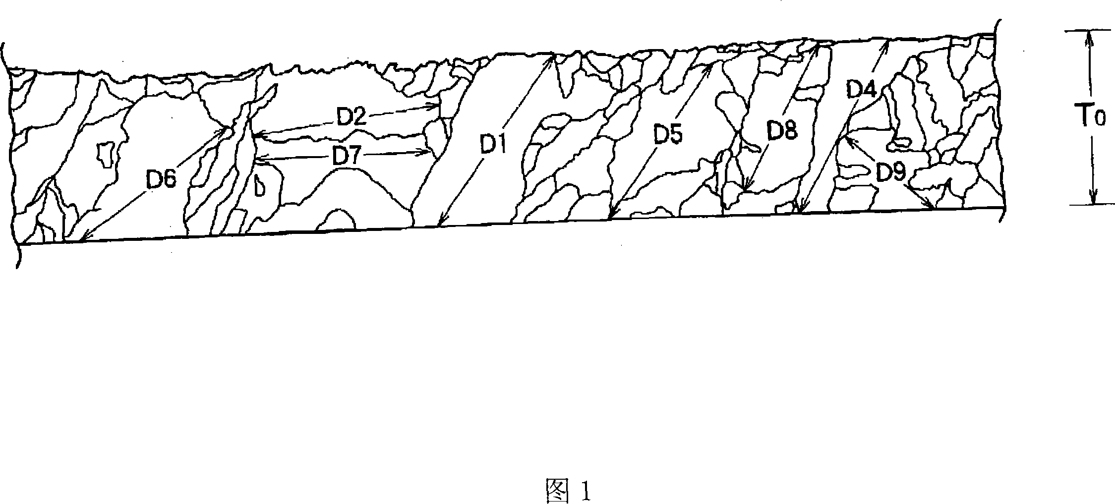
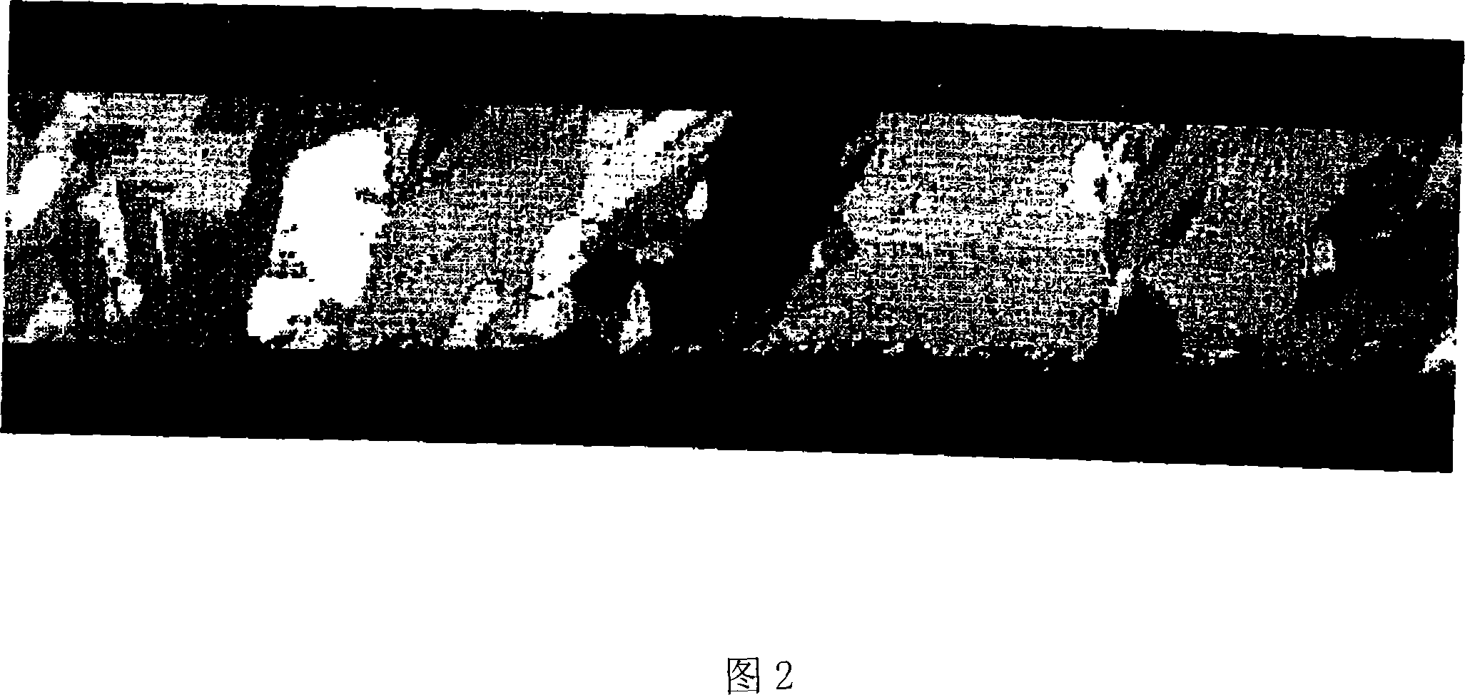
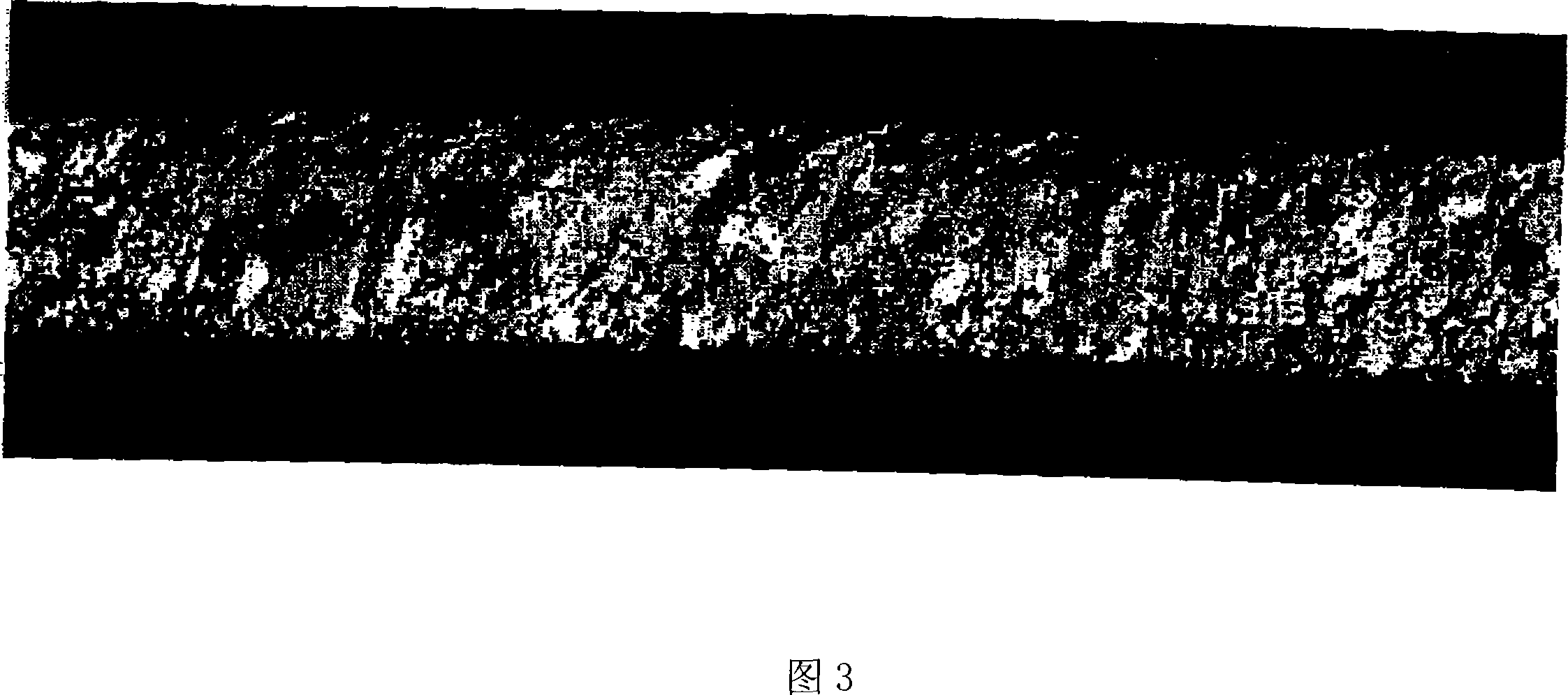

Image

  • Flexible printed wiring board and semiconductor device
  • Flexible printed wiring board and semiconductor device
  • Flexible printed wiring board and semiconductor device

Examples


Embodiment 1

Copper sulfate solution was used as the sulfuric acid-based copper electrolyte, and prepared so that the concentration of copper was 80 g / L, the concentration of free sulfuric acid was 140 g / L, the concentration of MPS-Na was 7 ppm, and the concentration of DDAC polymer (manufactured by Senka Co., Ltd., Unisens FPA100L) was 3 ppm. , An electrolytic solution with a chlorine concentration of 10ppm.

[0184] For the manufacture of low-profile electrolytic copper foil, a titanium cylinder can be used for the cathode, and DSA can be used for the anode. The liquid temperature is 50°C and the current density is 60A / dm. 2 Under the same conditions, a low-profile electrolytic copper foil with a thickness of 15 μm was continuously produced.

[0185] The average thickness of the obtained low-profile electrolytic copper foil is 15.0 μm, and its normal tensile strength is 39 kgf / mm 2 , the elongation rate was 7.2%. Tensile strength after heating at 180°C for 60 minutes is 35kgf / mm 2 , th...


PUM

PropertyMeasurementUnit
surface roughnessaaaaaaaaaa
thicknessaaaaaaaaaa
thicknessaaaaaaaaaa

Abstract

The flexible printed board of the present invention is characterized in that on a surface of a basal layer that is an insulation layer composed of resin which molecule is provided with imine structure and amide structure, etching an electrolytic copper foil of a laminating body forming by means of directly laminating a electrolytic copper foil containing a S surface and a M surface with various surface roughness, to form a wiring diagram, the surface roughness (Rzjis) on one side of the S surface is less than 1.0 [Mu]m and the glazing degree [Gs(60 DEG)] of the M surface is equal to or more than 400. By means of using the resin with imine structure and amide structure in the insulation molecule, the present invention provides a printed board with excellent mechanical property, thermal endurance and alkali tolerance etc., in particular a COF basal plate.

Description

technical field [0001] The present invention relates to a flexible printed circuit board and a semiconductor device using a base film composed of a resin having an imine structure and an amide structure in its molecule as an insulating film. In particular, the present invention relates to a base film composed of a resin having an imide structure and an amide structure in the molecule, a flexible printed circuit board and a semiconductor device formed instead of a polyimide film widely used as an insulating base. Background technique [0002] A flexible printed circuit board is used for mounting electronic components. The flexible printed circuit board is usually formed by forming a laminate of an insulating flexible film such as a polyimide film and a conductive metal foil such as an electrolytic copper foil, and then placing a laminate on the laminate. A photosensitive resin layer is formed on the surface of the conductive metal foil on the surface of the body, and the pho...

Claims


Application Information

Patent Timeline
Patent Type & Authority Applications(China)
IPC IPC(8): H05K1/03B32B15/08H01L23/498
CPCH05K2201/0154Y10T428/24917H01L2924/0002H05K1/0346H05K2201/0355H01L2924/00H05K1/02
Inventor 佐藤哲朗
Owner MITSUI MINING & SMELTING CO LTD
Learn More