Printing plate material and process for producing printing plate

A printing plate and substrate technology, applied in printing, printing plate, printing plate preparation, etc., can solve the problems of poor developing performance, unexpectable printing resistance, slow ink adhesion, etc., achieve excellent printing resistance, prevent Excellent effect on scratches and stains

Inactive Publication Date: 2008-08-27
KONICA MINOLTA MEDICAL & GRAPHICS INC
View PDF41 Cites 4 Cited by
  • Summary
  • Abstract
  • Description
  • Claims
  • Application Information

AI Technical Summary

Problems solved by technology

However, in such a configuration, although the handling performance is improved, the ink adhesion to the image portion of the printing plate at the time of printing (printing out) is slowed down, and on the other hand, the on-press development performance of the unexposed portion is also deteriorated. , the number of paper damage increases
Furthermore, the cover coat does not contribute to the improvement of the strength of the image part, so the improvement of the printing resistance cannot be expected.
[0011] Thus, it is difficult to simultaneously improve printing resistance, chemical resistance, and scratch and stain performance for on-press developing printing plate materials

Method used


Image

  • Printing plate material and process for producing printing plate

Examples


Embodiment 1

[0204]

[0205] The respective compositions in Table 1 were sufficiently mixed, stirred, and filtered to obtain coating liquids (1) to (5) for image forming layers having a solid content of 5%.

[0206] [Table 1]

[0207] Make up

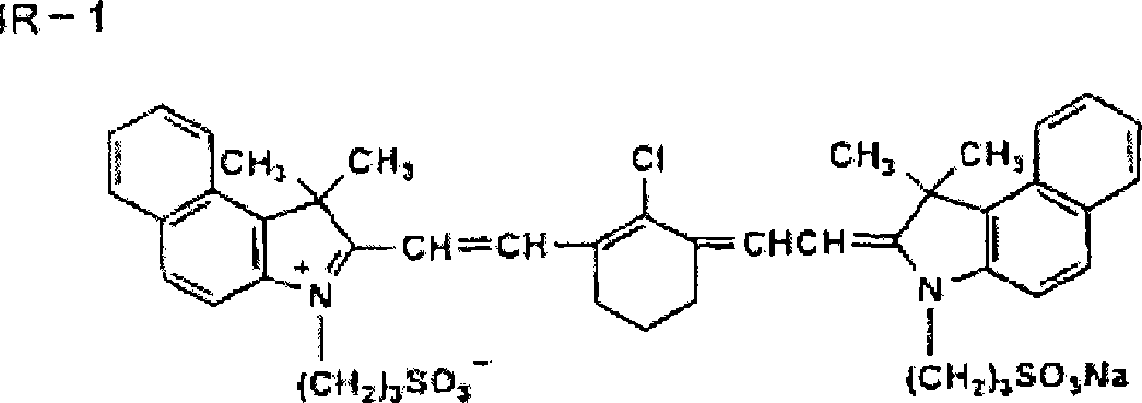
[0208] [Chemical formula 1]

[0209]

[0210]

[0211] On the surface of the lipophilic layer of the substrate 2, the image forming layer coating solutions (1) to (4) were respectively coated with a wire rod, and dried at 55°C for 3 minutes to obtain a positive printing plate material 1 ~4. Adjust the dry adhesion amount of the image forming layer to 0.8g / m 2 .

[0212] In addition, the above-mentioned image forming layer coating liquid (5) was coated on the surface of the hydrophilic layer of the substrate 3 with a wire rod, and dried at 55°C for 3 minutes to obtain a printing plate material 5 of a negative plate. Adjust the dry adhesion amount of the image forming layer to 0.8g / m 2 .

[0213]

[0214] For each of the obtained printing p...

Embodiment 2

[0238]

[0239] The respective compositions in Table 3 were sufficiently mixed, stirred, and filtered to obtain image forming layer coating liquids (6) to (9) having a solid content of 5%.

[0240] [table 3]

[0241] Make up

[0242] *1 Trimethylolpropane adduct of TDI, protective agent is oxime

[0243]

[0244] A film-forming acrylic emulsion with a solid content of 90% (WSA-900: manufactured by Dainippon Ink Co., Ltd.) and a stearic acid amide emulsion with a solid content of 10% (L-271: manufactured by Chukyo Oil Co., Ltd.) were mixed, and pure water was used. After diluting to a solid content of 5% in the liquid, it was filtered to obtain a coating liquid for a lipophilic cover coat layer.

[0245]

[0246] On the frosted surface of the above-mentioned base material 1, the image forming layer coating liquids produced in Examples 1 and 2 were respectively coated with a wire rod as shown in Table 4, and dried at 55°C for 3 minutes. The dry adhesion amount of the im...


PUM

PropertyMeasurementUnit
particle sizeaaaaaaaaaa
Adhesion amountaaaaaaaaaa

Abstract

The present invention provides a printing plate material comprising a base material and a thermal image forming layer and a constituent layer provided on the base material. The printing plate material is characterized in that the thermal image forming layer contains a silicate and a carbonate, the constituent layer is provided between the base material and the thermal image forming layer, and at least one of the constituent layer and the thermal image forming layer contains a photothermal conversion agent. The printing plate material has excellent print starting properties, printing durability, and scratch mark fouling preventive properties. The present invention also provided a process for producing a printing plate.

Description

Technical field [0001] The present invention relates to a printing plate material, in particular to a printing plate material that can form an image by computer to plate (PTC) method. Background technique [0002] At present, in the printing field, with the digitization of print image data, printing using the CTP method is in progress. However, in this type of printing, a cheap, easy to handle, and compatible with the so-called PS plate that has been used in the past is required. Printing plate material used in the CTP method of the characteristics of printing. [0003] In particular, in recent years, there is a demand for a general-purpose type that has direct imaging (DI) performance that does not require development with special agents, can be applied to printers with this function, and has the same performance as PS plates. Process-less print. [0004] In the image formation of the photosensitive plate in the athermal process, the infrared laser recording method with near inf...

Claims


Application Information

Patent Timeline
Patent Type & Authority Applications(China)
IPC IPC(8): B41N1/14G03F7/00G03F7/004G03F7/11
CPCB41C1/1016B41C2210/04B41C2210/08B41C2210/14B41C2210/22B41C2210/24B41C2210/26B41C2210/262B41C2210/264B41C2210/266
Inventor 森孝博
Owner KONICA MINOLTA MEDICAL & GRAPHICS INC
Why Eureka
Try Eureka