

Hard laminated film
A lamination and coating technology, applied in the direction of coating, layered products, metal material coating process, etc., can solve the problems of reduced surface properties, abnormal discharge, hindering high-efficiency ionization of gas, etc., to achieve wear resistance and Excellent lubricity, improved wear resistance or oxidation resistance
- Summary
- Abstract
- Description
- Claims
- Application Information
AI Technical Summary
Problems solved by technology
Method used
Image

Examples
Embodiment 1-1
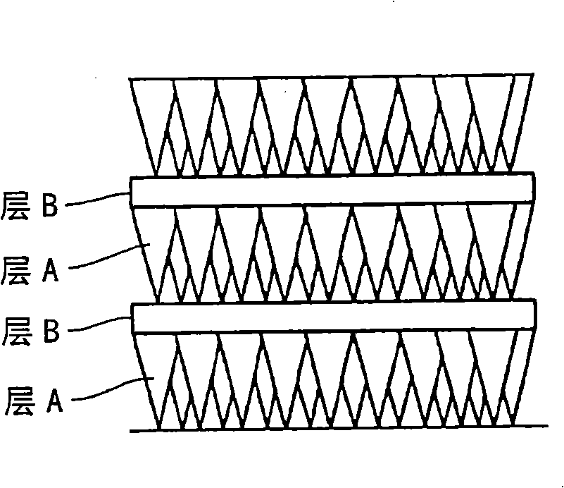
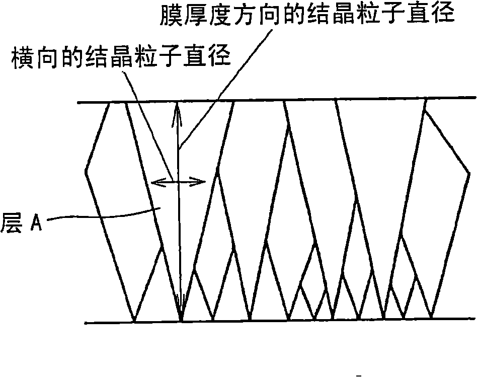
[0320] The influence of the crystal structure of layer B is investigated below. That is, it was confirmed that when a material having a cubic crystal rock-salt structure in the crystal structure is selected as the layer A, and a material having the same cubic rock-salt structure or a material having a different crystal structure is selected as the layer B, the crystal grains The presence or absence of the miniaturization effect.
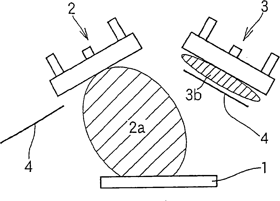
[0321] Specifically, using the above image 3 The shown sputtering film forming apparatus having two sputtering evaporation sources 2 and 3 forms a film having a laminated structure shown in Table 1. A cemented carbide (surface mirror-polished) for hardness measurement was used as the substrate 1 . After loading the substrate into the above image 3 After being inside the device, while heating the substrate temperature to the range of 400-500°C, vacuumize to 3×10 -3 Pa or less, after cleaning with Ar ions (pressure 0.6 Pa, substrate voltage 500 V...
Embodiment 1-2
[0328] Based on the results of this Example 1-1, the crystal structure of layer B was investigated in more detail. That is, it was confirmed that a hard coating material having a rock-salt cubic crystal structure such as TiAlN, CrN, and TiN was selected as the layer A, and a material having a crystal structure other than the rock-salt cubic crystal structure such as Cu, Co, SiN, and BN was selected as the layer B, or In the case of materials having a rock-salt cubic crystal structure such as CrN, MoN, WN, TaN, and AlN, or in the case where layer B is not provided, whether there is an effect of refining crystal grains and the strength of the film.
[0329] Specifically, and with the above image 3 The sputtering film-forming apparatus with the two sputtering evaporation sources 2 and 3 shown and the composite film-forming apparatus of arc and sputtering shown in FIG. 5 formed a film having the laminated structure shown in Table 2. As the substrate, the same cemented carbide (m...
Embodiment 1-3
[0336] Next, the effect of the thickness of the layer B made of a material having a crystal structure other than the rock-salt cubic crystal structure on the effect of refining the crystal grains of the layer A was examined.
[0337] As a film forming apparatus, a test material was prepared under the same conditions using the same sputtering apparatus and composite film forming apparatus as in Example 1-2 above. As the layer A, (Ti0.5Al0.5)N, CrN, and TiN, which are materials having a rock-salt cubic crystal structure and having high hardness, are selected, and as the layer B, SiN, BN, and Cu are selected. In the formation of layers such as SiN, BN, and Cu, Si, B 4 C and Cu targets.
[0338] In addition, by fixing the thickness of layer A at 30nm and changing the thickness of layer B in the range of 0.2 to 100nm, the effect of the thickness of layer B on the miniaturization effect of crystal grains was studied. About the test material after film formation, similarly to Examp...
PUM
| Property | Measurement | Unit |
|---|---|---|
| Thickness | aaaaa | aaaaa |
| Thickness | aaaaa | aaaaa |
Abstract
Description
Claims
Application Information