
Water treatment method and water treatment apparatus

A water treatment device and water treatment technology, which are used in water/sewage treatment, water treatment parameter control, oxidized water/sewage treatment, etc., and can solve problems such as inability to remove, increase in hydrogen peroxide concentration, and inability to correspond to BrO.

Inactive Publication Date: 2008-09-03
MITSUBISHI ELECTRIC CORP
View PDF2 Cites 4 Cited by
  • Summary
  • Abstract
  • Description
  • Claims
  • Application Information

AI Technical Summary

Problems solved by technology

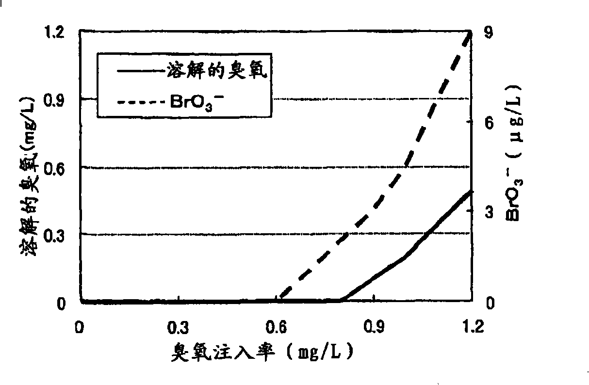
However, according to this method, since the ozone treatment is performed in the previous stage, BrO of about several μg / L is produced even if the concentration of dissolved ozone is controlled. 3 - , cannot correspond to the stricter BrO expected in the future 3 - control
In addition, BrO 3 - Once formed, it cannot be removed by ozone treatment, combined treatment with ozone and hydrogen peroxide, or ordinary activated carbon treatment
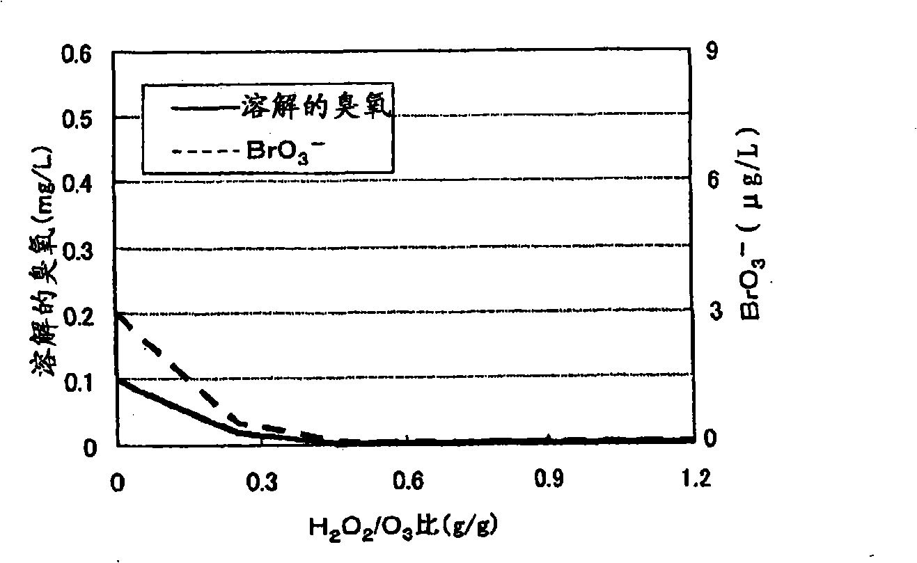
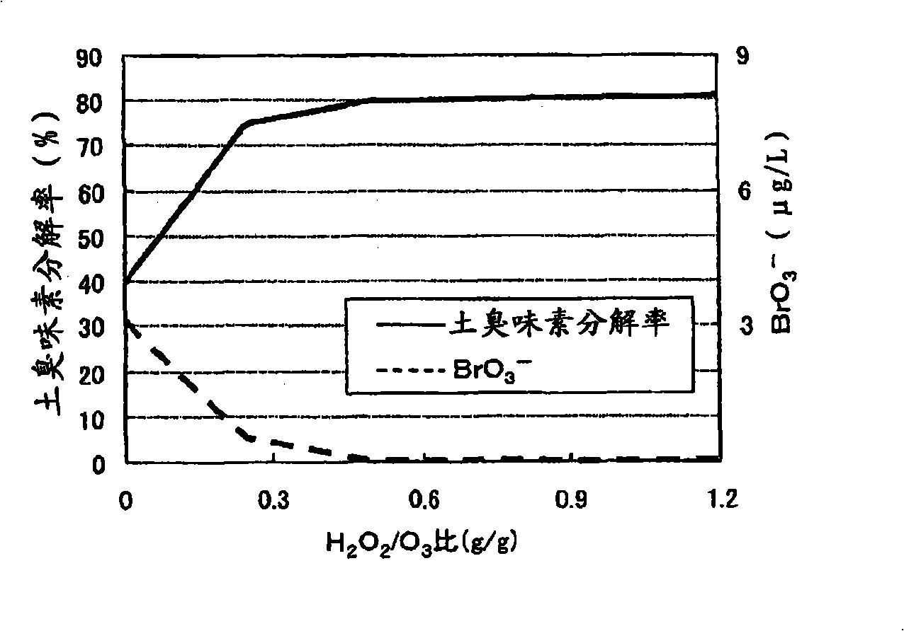
In addition, combined treatment with ozone and hydrogen peroxide is used in the latter stage, due to the inhibition of BrO 3 - For the formation of ozone, the relative ozone injection rate must reach excess hydrogen peroxide, but there is a disadvantage that the cost of hydrogen peroxide solution increases
As a result, the concentration of hydrogen peroxide remaining in the treated water increases, and the load to remove hydrogen peroxide in the subsequent activated carbon treatment increases.

Method used


Image

  • Water treatment method and water treatment apparatus
  • Water treatment method and water treatment apparatus
  • Water treatment method and water treatment apparatus

Examples


Embodiment approach 1

[0065] Fig. 6 is a flowchart illustrating a water treatment device according to Embodiment 1 of the present invention.

[0066] In Fig. 6, the water treatment device related to Embodiment 1 injects ozone into a part of the water to be treated before injecting hydrogen peroxide, and obtains an ozone injection rate calculation system that reaches the ozone injection rate of the prescribed dissolved ozone concentration; And after injecting hydrogen peroxide into the rest of the water to be treated, ozone is injected according to the obtained ozone injection rate to treat the water to be treated.

[0067] The treatment system has: a treated water inflow pipe 1 for making the treated water flow in; a treatment system ozone reaction tower 2 connected to the downstream side of the treated water inflow pipe 1 for making the treated water react with ozone; and the treatment system ozone The treatment system treatment water outflow pipe 3 connected to the reaction tower 2 is used to mak...

Embodiment approach 2

[0087] Figure 9 It is a flow chart for explaining the water treatment apparatus concerning Embodiment 2 of this invention.

[0088] exist Figure 9 Among them, the water treatment device involved in embodiment 2, in addition to setting the treated water absorbance meter 23, the treated water absorbance meter 24, the treated water absorbance signal line H and the treated water absorbance signal line I, replaces the ozone concentration monitor 16 and the dissolved Except for the ozone concentration signal line E, the configuration and operation of the apparatus are the same as those in Embodiment 1, and therefore their descriptions are omitted.

[0089] A device configuration different from that of Embodiment 1 will be described. The treated water absorbance meter 23 is arranged on the treated water branch pipeline 12 between the treated water flow meter 15 of the ozone injection rate calculation system and the ozone reaction tower 13 of the ozone injection rate calculation s...


PUM


Abstract

To minimize an amount of hydrogen peroxide required for controlling the production of bromic acid in an ozone / hydrogen peroxide treatment. The ozone / hydrogen peroxide treatment is performed at an ozone injection rate by which a predetermined dissolved ozone concentration of the water subjected to an ozone treatment alone can be maintained or at an ozone injection rate by which a specific ratio of absorbance at a specific wavelength of the water to absorbance at a specific wavelength of the water subjected to the ozone treatment alone can be achieved. It is preferable that the injection rate of hydrogen peroxide is 0.01 to 5 times the ozone injection rate on a mass basis.

Description

technical field [0001] The invention relates to a water treatment method and a water treatment device. Background technique [0002] Ozone treatment is the main method of deep water purification treatment. Ozone is effective for sterilization, deodorization and decolorization of treated water such as purified water, but bromide ions (Br - ) is oxidized to produce bromate ions (BrO 3 - ). BrO 3 - The generation, there is through Br - And the generation route of ozone (ozone route) and through Br - Two routes (radical routes) of radical species such as hydroxyl radicals (·OH) generated by self-decomposition of ozone. When using the ozone route, the Br in the treated water - , react with ozone to generate hypobromite ion (OBr - ), the hypobromite ion is further oxidized by ozone to generate BrO 3 - . When the free radical route is used, BrO is generated by free radicals and ozone 3 - . In addition, it has been reported that BrO 3 - Mainly generated by free rad...

Claims


Application Information

Patent Timeline
Patent Type & Authority Applications(China)
IPC IPC(8): C02F1/72C02F1/78
CPCC02F1/722C02F1/78C02F2101/306C02F2209/23
Inventor 安永望
Owner MITSUBISHI ELECTRIC CORP
Learn More