

Sputtering target, transparent conductive film and transparent electrode
A transparent conductive film and transparent electrode technology, applied in the field of sputtering targets, can solve problems such as the crystallization temperature or work function change of the transparent conductive film
- Summary
- Abstract
- Description
- Claims
- Application Information
AI Technical Summary
Problems solved by technology
Method used
Image

Examples
Embodiment 1
[0456] (1) Manufacture and evaluation of sputtering target
[0457] (i) Manufacturing of target
[0458]As the raw material for target production, indium oxide with an average particle size of 3.4 μm and a purity of 4N, zinc oxide with a purity of 0.6 μm and a purity of 4N, and tin oxide with a purity of 0.5 μm and a purity of 4N were mixed so that the atomic ratio [In / (In+Sn+Zn)] 0.53, the atomic ratio [Sn / (In+Sn+Zn)] is 0.17, and the atomic ratio [Zn / (In+Sn+Zn)] is 0.30, it is supplied to a wet ball mill, mixed and pulverized for 72 hours, and the raw material is obtained micro powder.
[0459] After granulating the obtained raw material fine powder, press-form it into a size with a diameter of 10 cm and a thickness of 5 mm, put it into a firing furnace, and burn it under oxygen pressure at 1400 ° C for 48 hours , to obtain a sintered body (target). The rate of temperature rise during firing was 3° C. / min.
[0460] (ii) Target evaluation
[0461] For the obtained target...
Embodiment 2~5、 and comparative example 1~7
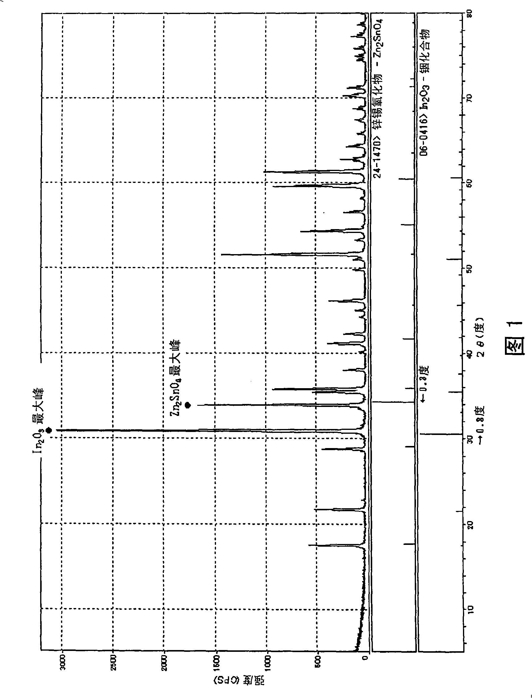
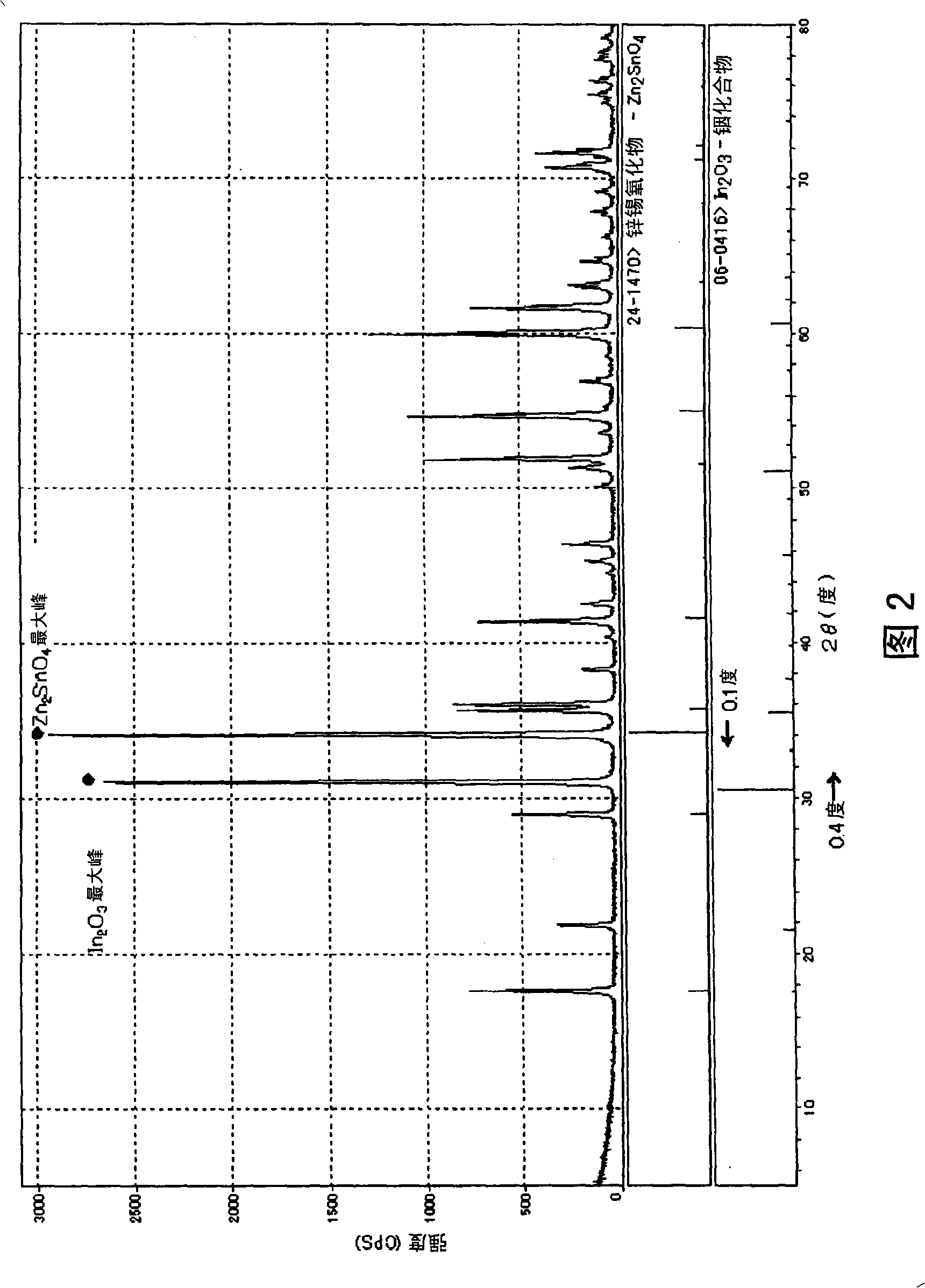
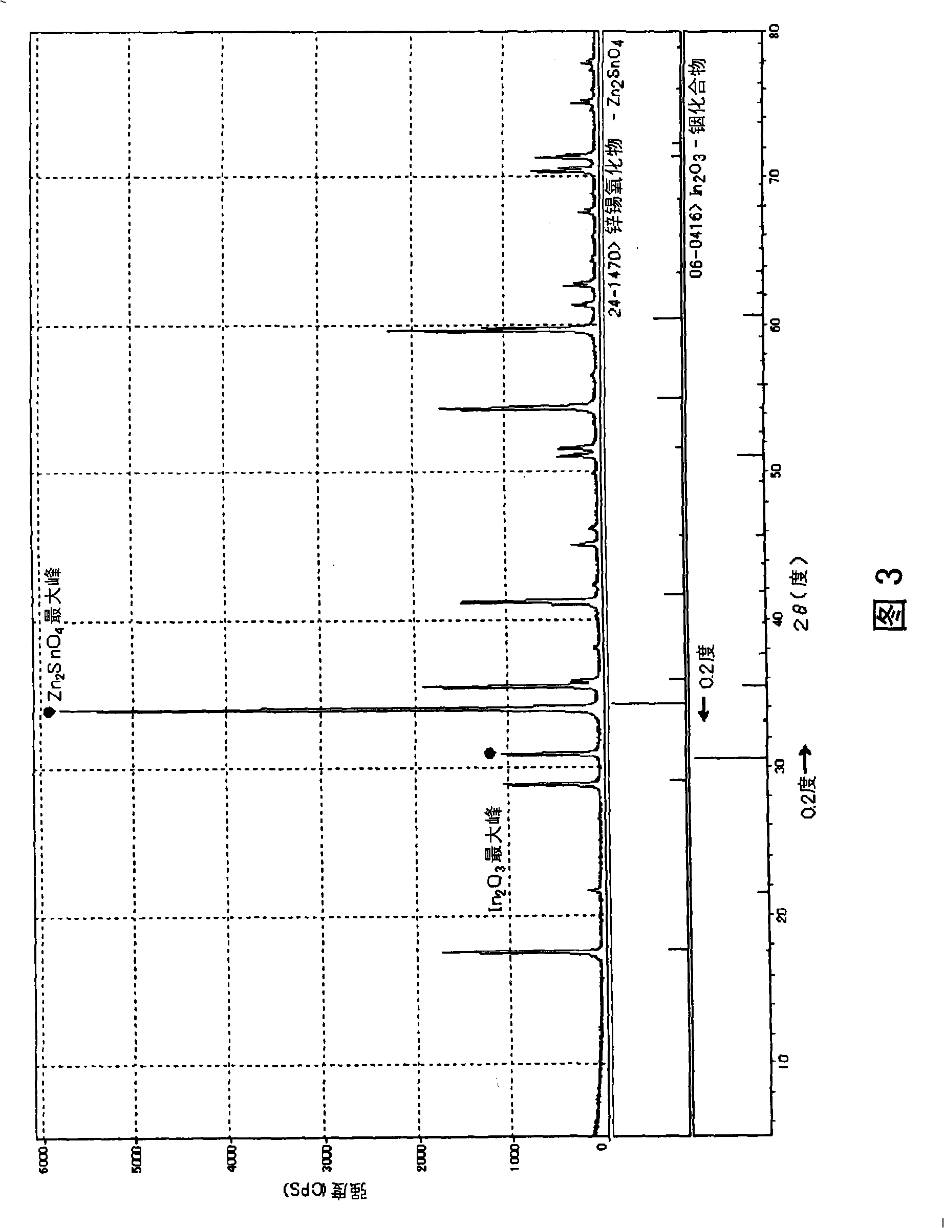
[0504] Table 1 shows the results of producing and evaluating targets in the same manner as in Example 1, except that the compounding ratio of metal oxides as raw materials was changed to the atomic ratio shown in Table 1. Graphs of X-ray diffraction on the targets obtained in Examples 3 and 4 are shown in FIGS. 2 and 3 .
[0505] In addition, an electron beam microanalyzer (EPMA) image measured in the same manner as in Example 1 for the sintered body obtained in Comparative Example 1 is shown in FIG. 6 .
[0506] In addition, in Comparative Examples 2, 4, and 5, since the discharge may become unstable during DC sputtering, RF sputtering was performed.
[0507] [Table 1]
[0508]
[0509] As can be seen from the results in Table 1, together with Zn 2 SnO 4 The spinel structure compound represented by In 2 o 3 The target of the indicated beryl structure compound has high theoretical relative density, low bulk resistance and high bending resistance.
[0510] In addition,...
Embodiment 6
[0512] (1) Manufacture of sputtering target
[0513] As raw materials, indium oxide with a purity of 4N and an average particle size of 2 μm, zinc oxide with a purity of 4N and 0.6 μm, and tin oxide with a purity of 4N and 0.5 μm were mixed so that the atomic ratio [In / (In+Sn+Zn)] was 0.64, The atomic ratio [Sn / (In+Sn+Zn)] was 0.18, and the atomic ratio [Zn / (In+Sn+Zn)] was 0.18, which were supplied to a wet ball mill, mixed and pulverized for 20 hours, and the raw material fine powder was obtained.
[0514]After granulating the obtained raw material fine powder, press-form it into a size with a diameter of 10 cm and a thickness of 5 mm, put it into a sintering furnace, and burn it at 1400 ° C for 48 hours under oxygen pressure to obtain Sintered body (target). The rate of temperature increase during firing was 180° C. / minute, and the rate of temperature decrease was 60° C. / hour.
[0515] (ii) Target evaluation
[0516] The obtained target was measured for density, bulk resi...
PUM
| Property | Measurement | Unit |
|---|---|---|
| Bulk resistance | aaaaa | aaaaa |
| Particle size | aaaaa | aaaaa |
| Diameter | aaaaa | aaaaa |
Abstract
Description
Claims
Application Information