
Preparation method of high coding efficiency optical encoder adapting to different wavelength

A codec and coding efficiency technology, which is applied in the field of optical codec production adapting to different wavelengths and high coding efficiency, can solve the problems of inconsistency, low coding efficiency, high cost, etc., and achieve low production cost and self-correlation performance Excellent, reduce production cycle effect

Inactive Publication Date: 2011-08-17
ARMY ENG UNIV OF PLA
View PDF1 Cites 0 Cited by
  • Summary
  • Abstract
  • Description
  • Claims
  • Application Information

AI Technical Summary

Problems solved by technology

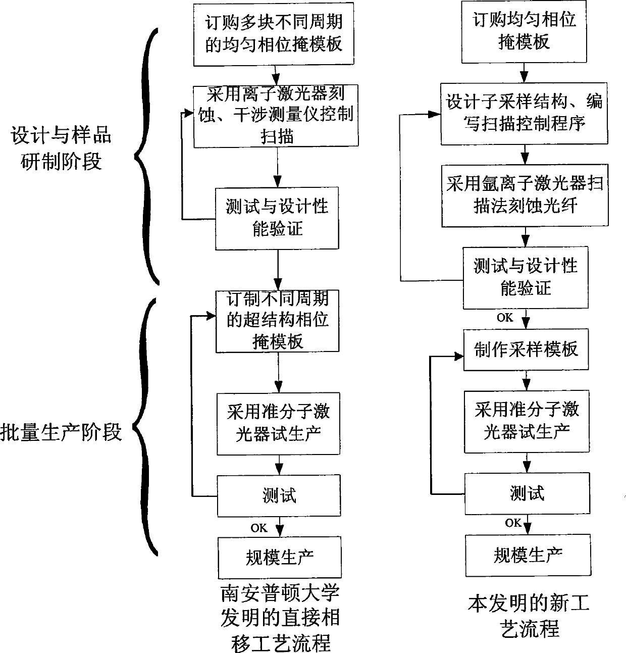
Using the direct phase shift technology proposed by the University of Southampton to make codecs with different wavelength channels requires phase masks of different periods, and the phase masks used to make fiber gratings are relatively expensive components in the whole set of equipment, so for C-band Dozens of WDM wavelength channels need dozens of phase masks for encoding and decoding, and the cost is extremely high
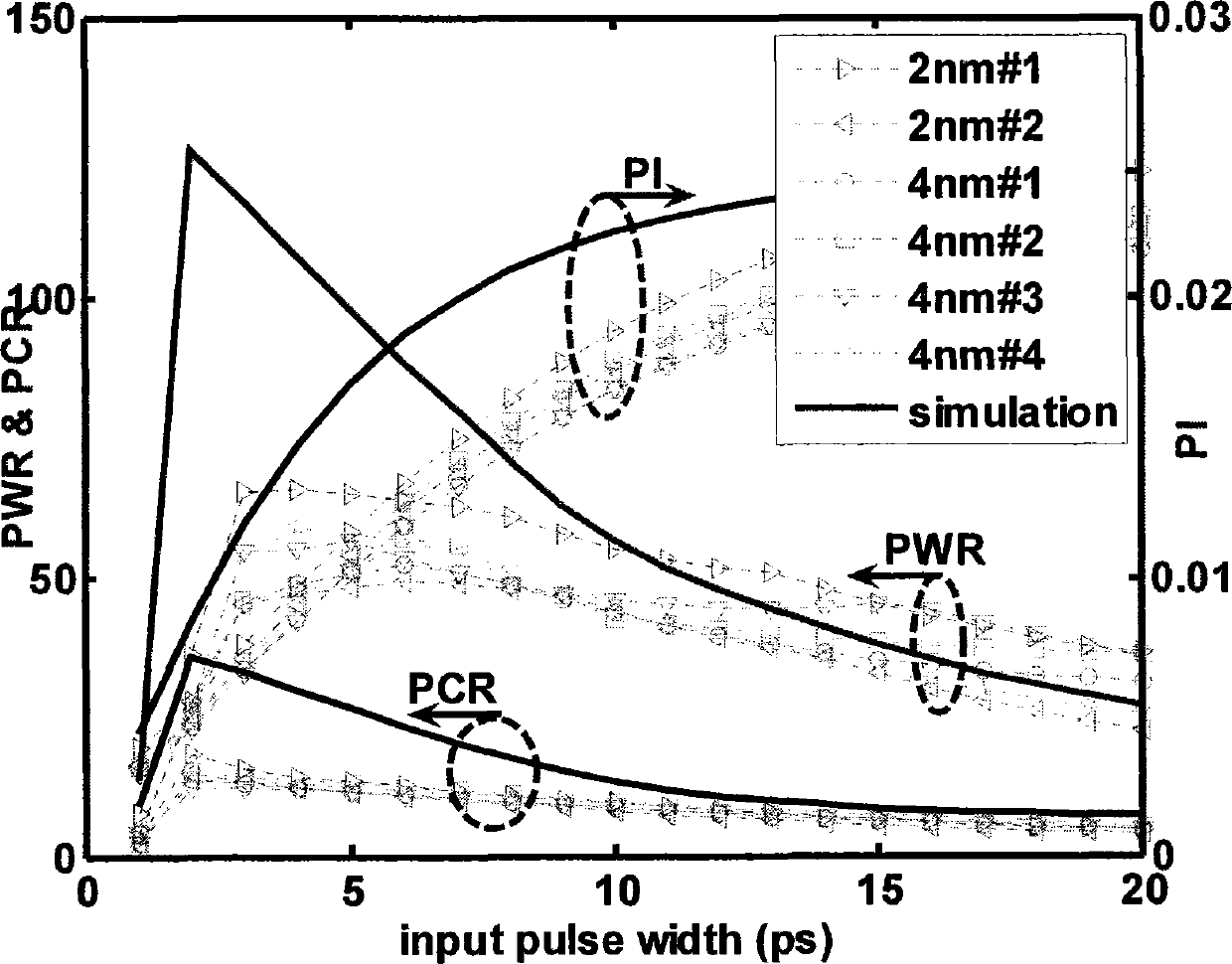
The equivalent phase shift technology proposed by Tsinghua University can use a phase mask to make codecs with different center wavelengths, but the coding efficiency is too low and has serious inconsistencies

Method used


Image

  • Preparation method of high coding efficiency optical encoder adapting to different wavelength
  • Preparation method of high coding efficiency optical encoder adapting to different wavelength
  • Preparation method of high coding efficiency optical encoder adapting to different wavelength

Examples


example 1

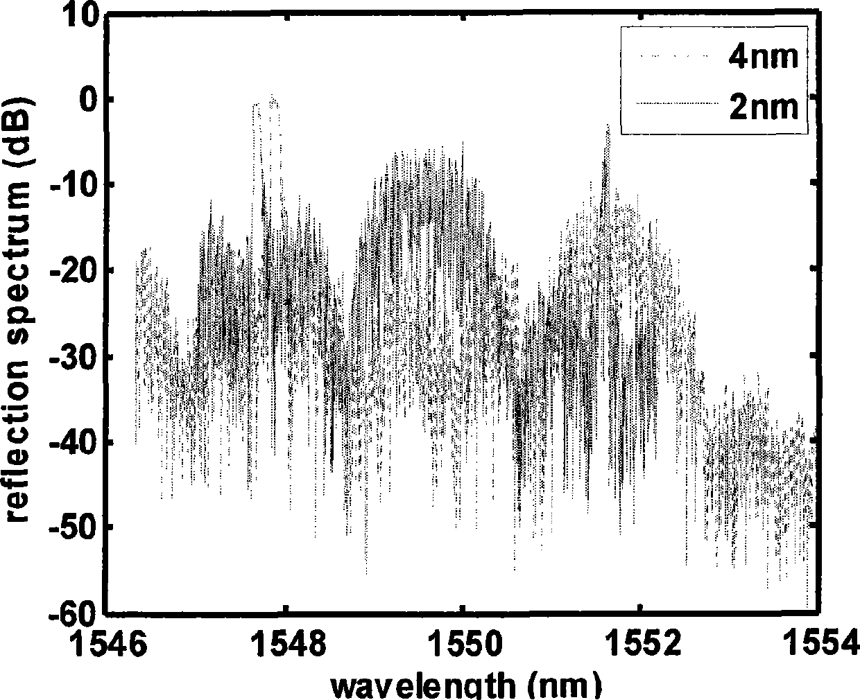
[0069] [Example 1] Central wavelength λ c = 1550nm codec

[0070] Since the phase mask period Λ mask =1070nm, grating period Λ=535nm, hydrogen-carrying optical fiber n eff =1.446, by formula λ Bragg =2Λn eff The 0th order wavelength λ=1548nm of the sampling grating can be obtained, so it is necessary to use the ±1 order of the sampling grating for phase encoding, and the wavelength interval Δλ=2nm; according to the following formula:

[0071] P = λ 2 2 n eff Δλ

[0072] This results in a sampling period P=0.4 mm. According to the following formula:

[0073] L chip = P [ Δλ BW ]

[0074] Draw L chip = 0.8 mm.

[0075] According to the code word of 127 bits, press formula:

[0076]

[0077] Determine the sampli...

example 2

[0078] [Example 2] Central wavelength λ c = 1552nm codec

[0079] Use the ±1 level of the sampling grating for phase encoding, and the wavelength interval Δλ=4nm; according to the following formula:

[0080] P = λ 2 2 n eff Δλ

[0081] This results in a sampling period P=0.2 mm. According to the following formula:


PUM


Abstract

The present invention relates to an optical encoder-decoder making method which is suitable for different wave lengths and high coding efficiency; a mask plate with uniform phase and a displacement platform with micrometer accuracy are adopted to design optical code division multiple access encoder-decoders with high coding efficiency according to different wave lengths and make channel encoder-decoders corresponding to the wave length channels so as to manufacture a channel encoder-decoder; the method comprises the following steps that: step 1: coding gratings with the following central wave lengths and chip lengths are designed according to the following setting parameters: the central wave length is shown in the right formula and the chip length is shown in the right formula; step 2: according to the parameters obtained from the step 1, positions of sampling points are determined according to the following formula Z<k> which is shown in the previous formula; step 3: the mask plate with uniform phase, an argon ion laser and a light path scanning system, the accuracy of which is smaller than 1Mum are adopted to control ultraviolet light scanning phase templates and photosensitive optical fibers according to the positions of sampling points Z<k>, therefore, the prototype manufacture of the phase encoder-decoder with the designated wave length and coding band width is completed via the steps from 1 to 3.

Description

technical field [0001] The invention relates to a manufacturing method of a superstructure optical fiber grating phase codec, which can design an optical code division multiple access codec with high coding efficiency for different wavelength channels, and only one piece of uniform phase codec is required to manufacture different wavelength channel codecs The mask plate and the displacement stage with micron precision have strong practical value. Background technique [0002] Encoder design and production is the key to OCDMA communication system. The traditional phase-shift grating is manufactured using the continuous phase writing technology [1-2], which makes the refractive index modulation between adjacent chips appear π phase shift by precisely controlling the time and position of the beam irradiation. The period of fiber gratings is generally around 530nm, so if you want to accurately control the phase change between adjacent chips, you must use nanoscale measurement a...

Claims


Application Information

Patent Timeline
Patent Type & Authority Patents(China)
IPC IPC(8): G02B6/02H04J14/02
Inventor 蒲涛王荣李玉权
Owner ARMY ENG UNIV OF PLA
Learn More