Hydrofluoroether compounds and processes for their preparation and use
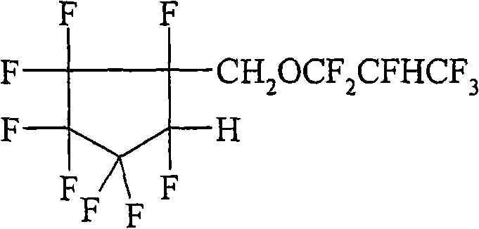
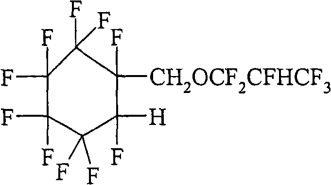
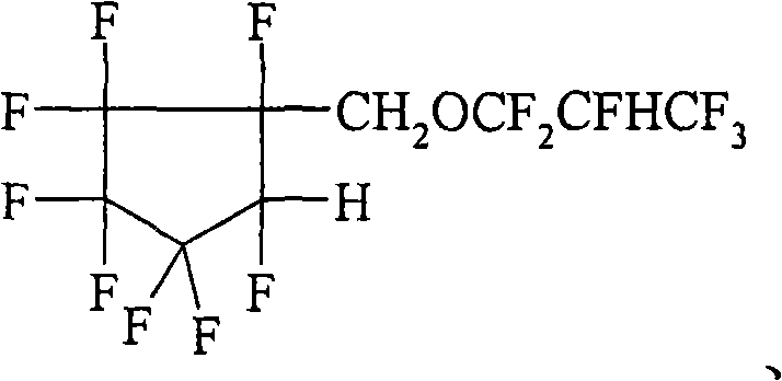
A kind of compound, technology of hydrofluoroether, applied in the field of preparing partially fluorinated ether compound
- Summary
- Abstract
- Description
- Claims
- Application Information
AI Technical Summary
Problems solved by technology
Method used
Image
Examples
preparation example Construction
[0060] Preparation of hydrofluoroether compounds
[0061] The hydrofluoroether compounds of the present invention are prepared by first performing a free radical addition reaction of at least one perfluoroalkene or perfluorovinyl ether starting compound with at least one hydrocarbon alcohol or addable fluorocarbon alcohol. This results in the formation of at least one fluoroalcohol intermediate. The fluoroalcohol intermediate is then anionized with at least one perfluoroalkene or perfluorovinyl ether modifying compound (which may be the same or different than the perfluoroalkene or perfluorovinyl ether used in the first addition reaction) addition to form at least one hydrofluoroether compound. Alternatively, when the alcohol is polyfunctional, the type of addition reaction can be reversed, wherein the first addition reaction is anionic addition and the second addition reaction is free radical addition. Therefore, the sequence of steps is non-limiting and can be modified t...
example
[0091] Objects and advantages of this invention are further illustrated by the following examples, but the particular materials and amounts thereof recited in these examples, as well as other conditions and details, should not be construed to unduly limit this invention. These examples are illustrative only, and are not intended to limit the scope of the appended claims.
[0092] All parts, percentages, ratios, etc. in the examples and in the rest of the specification are by weight unless otherwise indicated. Solvents and other reagents used were obtained from Aldrich Chemical Company (Milwaukee, Wisconsin) unless otherwise indicated.
[0093] In the following examples, a diastereomeric mixture is obtained due to the presence of two (or more) optical centers in the molecule. These diastereomers have boiling points very close to each other and therefore cannot be separated by distillation. In many cases, however, the above diastereomers are readily separated by gas chromatogr...
example 1
[0106] Preparation C 3 F 7 OCFHCF 2 CH 2 OCF 2 CFHCF 3
[0107] Using tert-amyl peroxybenzoate (1.0 g) as a free radical initiator, at 106 °C, via C 3 f 7 OCF=CF 2 (53g, 0.2mol) and methanol (63.7g, 2.0mol) reaction, preparation C 3 f 7 OCFHCF 2 CH 2 Oh. The reaction product mixture was washed with water and distilled, the fraction b.r. = 115-117°C was used in the next step.
[0108] In a 500 mL round bottom flask equipped with a magnetic stir bar, gas inlet tube, and solid carbon dioxide / acetone condenser, place C 3 f 7 OCFHCF 2 CH 2 OH (18.5 g, 0.062 mol), potassium carbonate (1.67 g, 0.012 mol) and anhydrous acetonitrile (73.1 g). While stirring, the resulting reaction mixture was heated to 45°C, and the addition of HFP (10 g) was started via the inlet tube. After 10 minutes, the internal temperature of the reaction mixture reached 54°C, and the addition of HFP was stopped. After cooling back to 45°C, another 10 g of HFP was added. ...
PUM
| Property | Measurement | Unit |
|---|---|---|
| Flash point | aaaaa | aaaaa |
| Boiling point | aaaaa | aaaaa |
Abstract
Description
Claims
Application Information
 - R&D
- Intellectual Property
- Life Sciences
- Materials
- Tech Scout
- Unparalleled Data Quality
- Higher Quality Content
- 60% Fewer Hallucinations
Browse by: Latest US Patents, China's latest patents, Technical Efficacy Thesaurus, Application Domain, Technology Topic, Popular Technical Reports.
© 2025 PatSnap. All rights reserved.Legal|Privacy policy|Modern Slavery Act Transparency Statement|Sitemap|About US| Contact US: help@patsnap.com


