Eureka AIR delivers breakthrough ideas for toughest innovation challenges, trusted by R&D personnel around the world.

Active heat reclaiming method and device for diesel engine particulate drip catcher

A particulate filter and diesel engine technology, applied in the direction of machines/engines, mufflers, exhaust devices, etc., can solve problems such as unreliable performance, complex systems, and affecting filter elements, etc., to achieve uniform cross-sectional temperature, uniform temperature distribution, The effect of speeding up regeneration

Inactive Publication Date: 2008-09-24
HUNAN UNIV
View PDF2 Cites 14 Cited by
  • Summary
  • Abstract
  • Description
  • Claims
  • Application Information

AI Technical Summary

Problems solved by technology

However, the fuel injection combustion-supporting regeneration method has the following disadvantages: ① Since the fuel must have a relatively high pressure (otherwise the spray cannot be formed in the nozzle, so that ignition and normal combustion cannot be performed), so it is necessary to set up a high-pressure oil pump and the driving equipment of the oil pump, The system is quite complicated; ②Based on the temperature limit that the filter element can withstand, the injected fuel flow rate is not large, and due to ignition requirements, the atomized fuel must have a suitable atomized particle size and droplet size distribution. The atomization requirements are very high. Correspondingly, the nozzle must be loaded with a high injection pressure, so the size of the nozzle hole and other parts is generally small. Such a small flow fuel atomization equipment is difficult to design and the processing performance The second is that it is easy to block and the performance is very unreliable; ③The fuel droplets are liquid before ignition in the combustion zone, while the oxygen content in the engine exhaust is not high, the ignition environment is poor, the fuel is not easy to ignite, and the requirements for the ignition coil It is very harsh, and it is likely that before the ignition is successful, a lot of liquid fuel oil has accumulated on the inner wall of the main combustion zone. Once the ignition is successful, these liquid oils will participate in the combustion, causing high temperature damage to the DPF, and even a hidden danger of explosion. The system is difficult to stabilize; ④ It is difficult to match the fuel droplets with the airflow. It is very difficult to ensure efficient and stable combustion of fuel in the main combustion zone with low density and low oxygen content. As a result, a large part of the fuel is directly discharged into the atmosphere without burning at all. The essence of the exhausted hydrocarbons is secondary pollution; ⑤The fuel flame temperature field is not easy to adjust, and is greatly affected by the driving state of the vehicle, and it is easy to form a local high-temperature area with a high peak value, which affects the overall efficiency of filter element regeneration and shortens its temperature. life

Method used


Image

  • Active heat reclaiming method and device for diesel engine particulate drip catcher
  • Active heat reclaiming method and device for diesel engine particulate drip catcher
  • Active heat reclaiming method and device for diesel engine particulate drip catcher

Examples


Embodiment 1

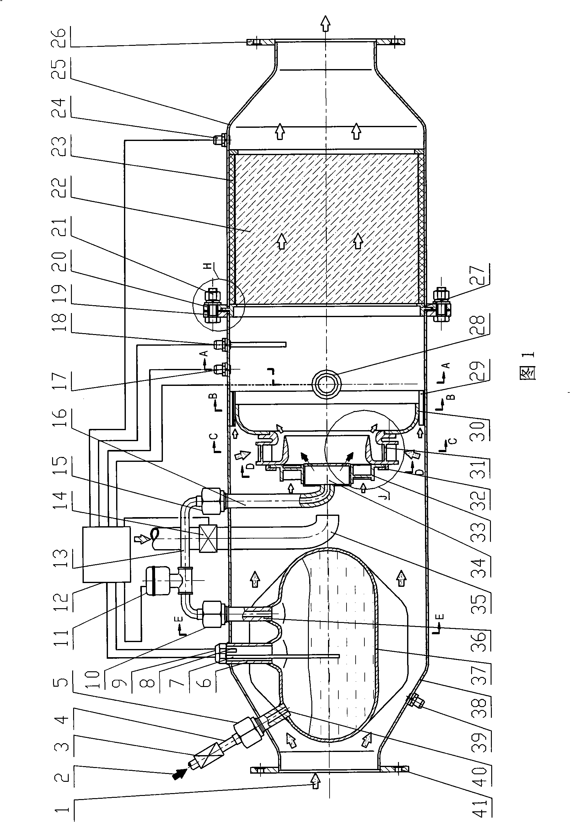
[0066] Embodiment 1: The active thermal regeneration method of the diesel particulate filter is: use the exhaust heat of the diesel engine or supplement it with electric heating to make the liquid fuel in the fuel seal tank form a high-temperature saturated vapor with pressure; when the front and rear pressures of the filter element in the exhaust channel When the pressure difference displayed by the sensor reaches the preset value, the central control unit sends a regeneration command to open the fuel outlet valve so that the saturated high-pressure fuel vapor in the fuel seal tank enters the nozzle through the fuel outlet valve, sprays into the main combustion area, and ignites. The nozzle starts to flash and ignites the gaseous fuel vapor; under the action of the double-stage cyclone, the flame is kept in the main combustion area, generating high-temperature gas, flowing through the filter element, igniting the particulate matter deposited on the filter element, until the fro...

Embodiment 2

[0068] Embodiment 2: As shown in FIG. 1, the shell of the particle trap is divided into two parts, namely, the shell of the trapping section 25 and the shell of the regeneration section 38. The position is provided with connecting ring 27, and its function is to fix filter core 23 on the one hand, and on the other hand is to two ends housing 25,38 docking positions (as Figure 7 shown).

[0069] A filter element 22 and a filter element vibration-damping insulation layer 23 are installed inside the trapping section housing 25, and a third pressure sensor 24 is arranged downstream of the filter element 23. Lan 26.

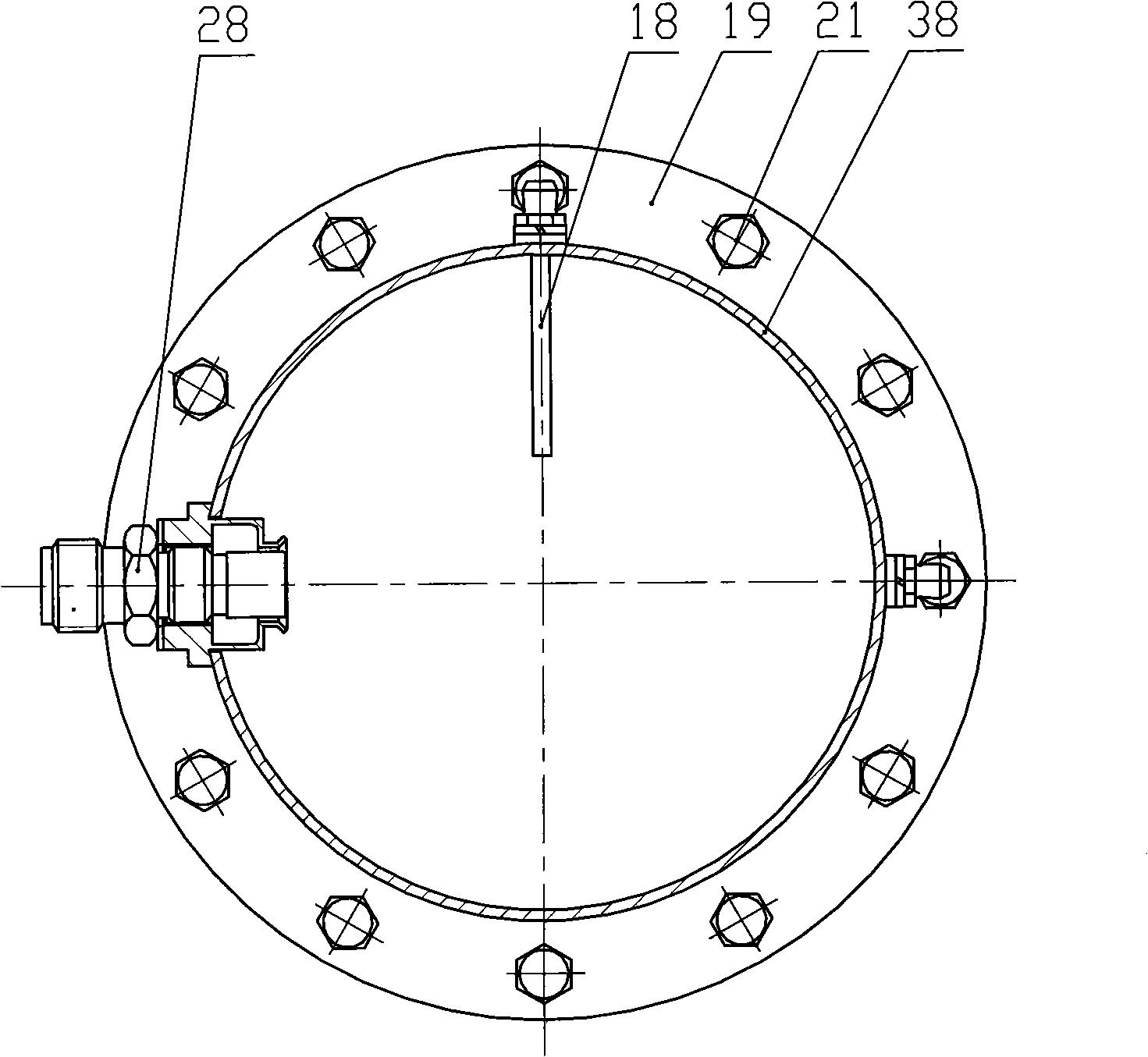
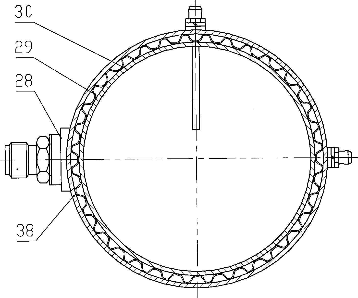
[0070] A flange 41 is provided at the inlet of the casing 38 of the regeneration section, and a fuel tank 37, a secondary air input pipe 35, a fuel nozzle 34, a primary cyclone 33, a secondary cyclone 31, and a head ring 30 are installed inside. and other components. An oxygen content sensor 39 , an ignition nozzle 28 , a second pressure sensor 17 and a temperatur...

Embodiment 3

[0077] Embodiment 3: the difference between this program and embodiment 2 is that 1. the fuel used is different, and what is stored in the fuel tank 37 is the fuel with a boiling point higher than the engine exhaust temperature, such as diesel oil; 2. in the fuel tank 37, an additional An electric heating facility is provided, that is, an electric heating wire 53 is provided in the fuel tank 37, see for details Figure 18 .

[0078] A heating wire 53 and its installation rod 51 are arranged in the fuel tank 37 , and the installation rod 51 is fixed on the lead-out seat 9 . Because the exhaust gas 1 of the diesel engine does not necessarily make the diesel oil boil to generate high-pressure steam, after the regeneration program starts, the central control unit 12 energizes the heating wire 53 to heat the fuel until the pressure sensor 50 shows that the pressure in the fuel tank 37 reaches the preset value , at this time, the fuel tank 37 has high temperature and high pressure s...


PUM


Abstract

The invention relates to an active thermal regenerative method and a device of a collector for diesel micro particle. The method is as follows: liquid fuel, the boiling point of which is higher than normal temperature, is put into the tail gas of an engine or made into high pressure fuel vapor by being heated by electricity; after CPU sends a regeneration instruction, the oxygen content of regenerative environment is adjusted by supplementing auxiliary air and the fuel under high temperature steam enters combustion zone; meanwhile, an ignition plug begins to jump spark; fuel vapor is ignited Under the action of a twin-stage reverse whirl cone, premised flame is fixed on a proper position; heat from fuel burning makes gas flow temperature rise until the temperature of microparticle on filter element is above inflammation point; the microparticle on deposit is ignited when high temperature air flow passes by the filter element; the fuel should be continuously supplied until the microparticle on the deposit is burnt out; and a regenerative cycle is finished. In order to avoid the extreme high temperature of primary chamber part outside the collector, a gaseous film cooling structure is arranged. The active thermal regenerative method and device of the collector for diesel microparticle is easy to be ignited and has the characteristics of stable burning, efficient burning, strong anti-interference ability, little secondary pollution and stable action.

Description

technical field [0001] The invention relates to a regeneration method of a diesel engine exhaust post-treatment device and its device, in particular to an active thermal regeneration method of a diesel particulate filter (DPF) and its device. technical background [0002] Particulate matter (PM), which is mainly composed of soot and other substances, exists in the exhaust of diesel engines. These particulate matter are very harmful to the environment and are one of the main pollution sources of urban air. Therefore, the importance of diesel engine exhaust particulate matter emission control has attracted more and more people's attention and attention, and many countries in the world are gradually implementing stricter diesel engine PM emission standards and regulations. [0003] Among many diesel PM emission control technologies, Diesel Particulate Filter (DPF, also known as particulate filter) is considered to be one of the most promising technologies. The main idea is to ...

Claims


Application Information

Patent Timeline
Patent Type & Authority Applications(China)
IPC IPC(8): F01N3/025
Inventor 龚金科王曙辉鄂加强余明果伏军吴钢吁璇
Owner HUNAN UNIV
Why Eureka
Eureka Blog
Learn More