Fuel oil, gas energy-saving fine purification method and device

A technology for purifying treatment and gas, applied in combustion air/combustion-air treatment, charging system, combustion engine, etc., can solve the problem that the electromagnetic field frequency and output power of the treatment device are not determined, the molecular shape change cannot achieve the desired effect, and the electromagnetic Problems such as the limitation of the effect of the fuel-saving exhaust gas purification device to achieve the effect of improving the degree of refinement, improving the combustion value and saving fuel

Active Publication Date: 2008-09-24
陈良璞 +1
View PDF6 Cites 4 Cited by
  • Summary
  • Abstract
  • Description
  • Claims
  • Application Information

AI Technical Summary

Problems solved by technology

[0003] Because the frequency range and magnetic field strength of the electromagnetic field produced by the automobile fuel economizer of the existing electromagnetic field method are not correct and suitable, it cannot meet the requirements of different types of fuels for the frequency and magnetic field strength of the electromagnetic field.
The effects of these electromagnetic fuel-saving exhaust gas purification devices are limited, resulting in little or no effect of these electromagnetic fuel-saving devices, which are doubted or denied by the market
For example, application

Method used


Image

  • Fuel oil, gas energy-saving fine purification method and device
  • Fuel oil, gas energy-saving fine purification method and device
  • Fuel oil, gas energy-saving fine purification method and device

Examples


Example Embodiment

[0026] Example 1:

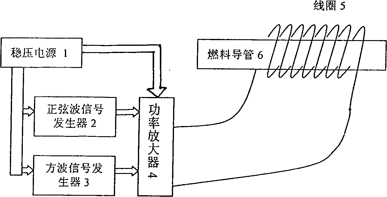
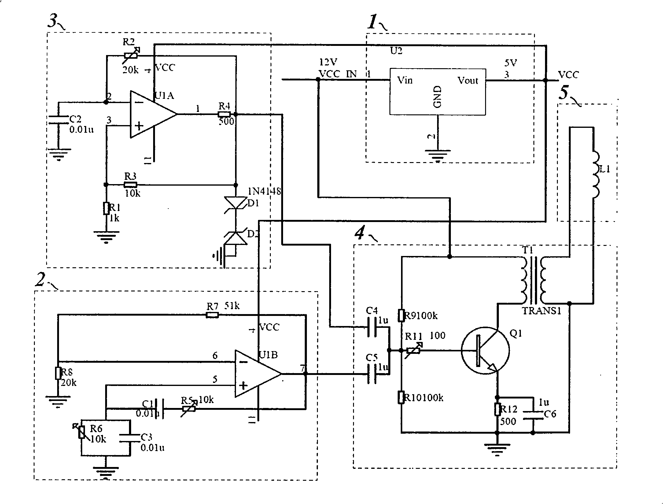
[0027] The voltage stabilizing circuit 1 is composed of a three-terminal voltage stabilizing chip U2, which converts the 12V DC power supply of the car battery into a stable 5V DC power supply for the sine wave signal generator 2 and the square wave signal generator 3, and its input terminal is connected to the car battery 12V DC power supply, the output terminal of which is connected to the power supply pins of operational amplifiers U1A and U1B.

[0028]Sine wave signal generator 2 is composed of resistors R5, R6, R7, R8, capacitors C1, C3, and operational amplifier U1B. C1 and R5 are connected in series with C3 and R6 in parallel to form a positive feedback loop. R7 and R8 form a negative feedback loop, which is the same phase of operational amplifier U1B. The input terminal is connected to capacitors C1, C3, and resistor R6. The other end of resistor R5 and R7 is connected to the output terminal of operational amplifier U1B. The inverting input terminal of ...

Example Embodiment

[0045] Example 2:

[0046] The second embodiment of the present invention is a gas-saving device for household natural gas stoves, and the gas oil flow rate V is 1 (g / s). Natural gas is based on methane (C 1 H 4 ) Is a mixture of the main body.

[0047] Methane (C 1 H 4 ) The relative atomic weight M of the molecule takes an integer approximation: 1×12+4×1=16

[0048] Methane (C 1 H 4 ) The bonding bond between molecules is "C-C". Check Appendix 1 (the table of van der Waals force constants for bonding bonds between commonly used molecules) to know that the van der Waals force constant of the "C-C" bond is 4.5 to 5.6. Generally speaking, as the number of C atoms increases, the molecular weight of alkane molecules increases, and the greater the van der Waals force, the tighter the molecules; conversely, as the number of C atoms decreases, the molecular weight decreases, and the van der Waals force decreases. Methane (C 1 H 4 ) The molecule contains only one C atom, so the smaller v...


PUM


Abstract

The present invention provides a fuel oil-gas energy-saving purifying processing method and a device thereof, which solves the problem of the prior method and device of not being capable of achieving ideal effect for liquid molecule morphological change. Liquid passes a conduit the outside of which is wrapped with a winding (5); the liquid passes the current power in watt of the winding (5) and then passes the alternating current on-off frequency in kHz. V is the flow of the liquid; the unit is g/s; M is the relative atomic weight of liquid molecule; K is the Van der Waals force constant of the liquid molecule.

Description

Technical field: [0001] The invention relates to a fluid magnetization method and device, in particular to a fuel oil and gas magnetization method and device. Background technique: [0002] At present, there are automobile fuel economizers made of permanent magnets on the market, which use gas molecules to change their shape after passing through a magnetic field, which helps to fully burn and save energy. Due to the insufficient magnetic flux of the permanent magnetic material, its magnetization effect is limited, and the fuel saving performance is not ideal, so the market acceptance of this type of automotive fuel economizer is not high. At present, there are also automotive fuel economizers with electromagnetic field methods on the market. The technical solutions are: the electromagnetic coil is wound on the fuel passage, and when the fuel flows through the center of the electromagnetic coil, the magnetized fuel burns more efficiently in the internal combustion engine. C...

Claims


Application Information

Patent Timeline
IPC IPC(8): F02M27/04
CPCY02T10/126Y02T10/12
Inventor 甘国工蒋岚陈良璞
Owner 陈良璞
Why Eureka
Try Eureka