
Plane type fuel cells

A fuel cell group, planar technology, applied in the direction of fuel cell groups, fuel cells, fuel cell additives, etc., can solve the problems of gas inaccessibility, affecting the output power of fuel cells, blocking, etc., to save manufacturing costs and improve Backwater effect, simple manufacturing method

Active Publication Date: 2008-11-19
IND TECH RES INST
View PDF4 Cites 5 Cited by
  • Summary
  • Abstract
  • Description
  • Claims
  • Application Information

AI Technical Summary

Problems solved by technology

[0010] In addition, Japanese Patent No. WO 2005 / 112172A1 discloses a fuel cell in which liquid fuel gasification components are supplied to the catalyst layer, which discloses that the anode structure of the fuel cell needs to include a fuel storage tank, a fuel gasification layer and Vaporized fuel storage chambers, etc., so that liquid fuel can be vaporized, and a moisture-retaining layer with appropriate moisture permeability and air permeability is provided on the cathode side, but the moisture-retention layer is a porous material with uniform micro-pores. It is very easy to block the pores on the moisturizing layer due to condensation of water vapor, so that the gas cannot enter and affect the output power of the fuel cell

Method used


Image

  • Plane type fuel cells
  • Plane type fuel cells
  • Plane type fuel cells

Examples


Embodiment Construction

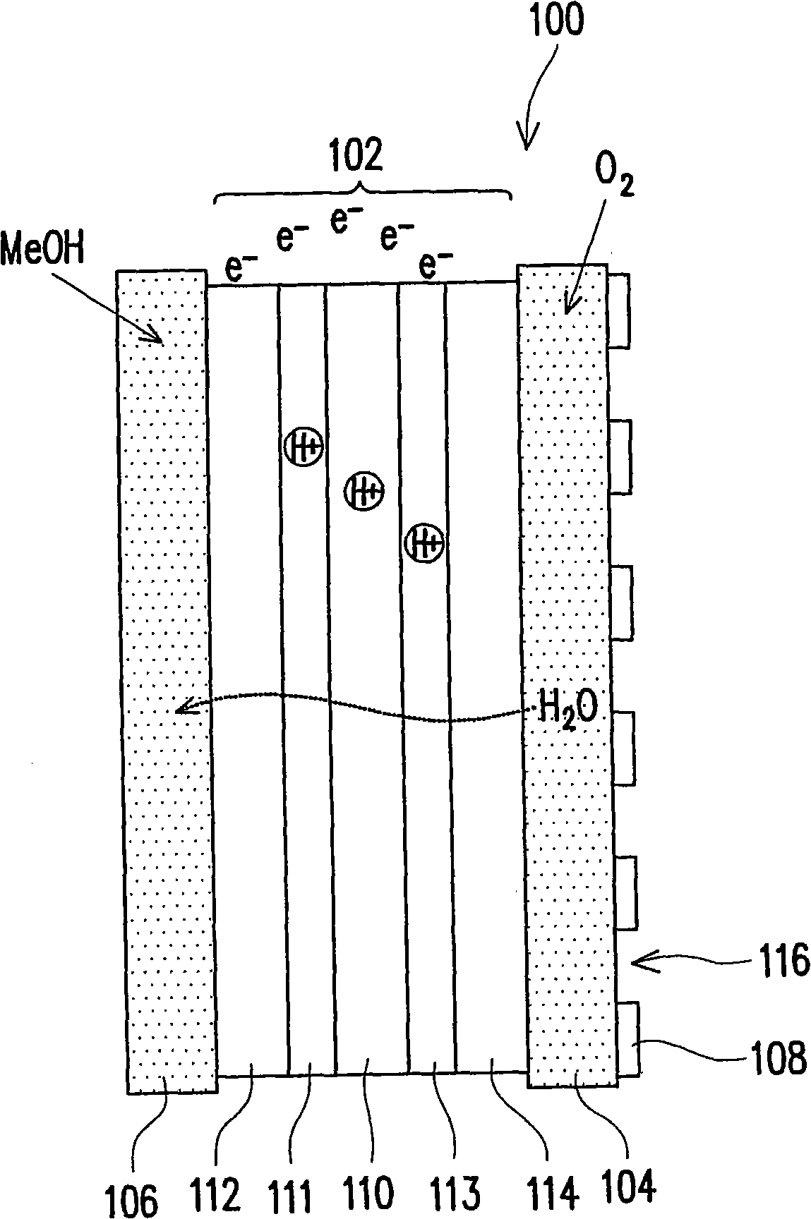
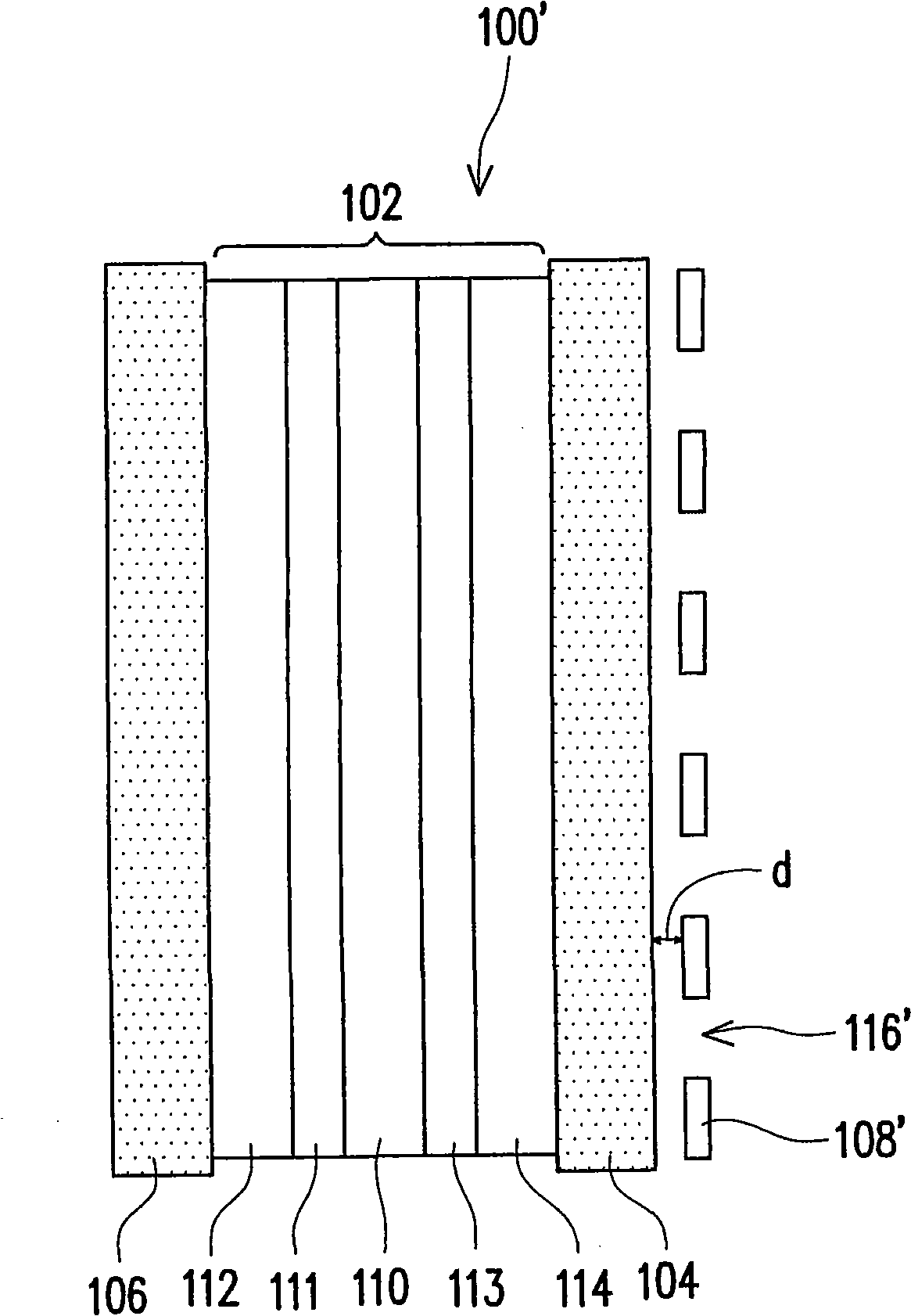
[0040] figure 1 It is a schematic structural diagram of a planar fuel cell stack according to an embodiment of the present invention. Please refer to figure 1 , the planar fuel cell assembly 100 includes a membrane electrode assembly (MEA) 102 , a cathode porous collector layer 104 , an anode porous collector layer 106 and a gas barrier material layer 108 . Wherein, the thin film electrode assembly 102 has a proton exchange membrane 110, an anode catalyst layer 111, a cathode catalyst layer 113, an anode gas diffusion layer 112 and a cathode gas diffusion layer 114, and the anode catalyst layer 111 and the cathode catalyst layer 113 are respectively arranged on the proton exchange membrane On both sides of 110 , an anode gas diffusion layer 112 and a cathode gas diffusion layer 114 are respectively disposed on the anode catalyst layer 111 and the cathode catalyst layer 113 . The material of the anode catalyst layer 111 is, for example, platinum / ruthenium alloy (Pt / Ru), carbo...


PUM

PropertyMeasurementUnit
thicknessaaaaaaaaaa
thicknessaaaaaaaaaa
widthaaaaaaaaaa

Abstract

Disclosed is a flat fuel cell assembly, comprising a membrane cell assembly, a cathodic porous collector layer, an anodic porous collector layer and an air blocking material layer; wherein the membrane cell assembly is provided with a proton exchange membrane, an anodic catalyst layer, a cathodic catalyst layer, an anodic gas diffusion layer and a cathodic gas diffusion layer; the anodic catalyst layer and the athodic catalyst layer are respectively arranged at the two sides of the proton exchange membrane; the anodic gas diffusion layer and the cathodic gas diffusion layer are arranged respectively on the anodic gas diffusion layer and the cathodic gas diffusion layer; the cathodic porous collector layer is arranged at one side of the cathodic gas diffusion layer and the anodic porous collector layer is arranged at one side of the anodic gas diffusion layer; in addition, the air blocking material layer is arranged on the cathodic gas diffusion layer and is provided with at least one hole which is exposed at the surface of the cathodic porous collector layer.

Description

technical field [0001] The present invention relates to a fuel cell structure, and in particular to a planar fuel cell stack. Background technique [0002] With the advancement of industry, the consumption of traditional energy such as coal, oil and natural gas continues to rise. Due to the limited stock of natural energy, it is necessary to develop new alternative energy to replace traditional energy, and fuel cells are an important and unique energy. A choice of practical value. [0003] In simple terms, a fuel cell is basically a power generating device that converts chemical energy into electrical energy using the reverse reaction of electrolysis of water. Taking a proton exchange membrane fuel cell as an example, it is mainly composed of a membrane electrode assembly (MEA for short) and two electrode plates. The thin film electrode group is composed of a proton exchange membrane (proton exchange membrane), an anode catalyst layer, a cathode catalyst layer, an anode ga...

Claims


Application Information

Patent Timeline
Patent Type & Authority Applications(China)
IPC IPC(8): H01M8/24H01M8/04H01M8/02H01M8/10H01M4/86H01M8/023H01M8/04119H01M8/1004H01M8/2418H01M8/2465
CPCY02E60/521Y02E60/50
Inventor 康顾严戴椿河赖秋助许盈盈蔡英文
Owner IND TECH RES INST
Learn More