

R-Fe-B porous magnet and method for producing the same
A manufacturing method, porous technology, applied in the direction of inductor/transformer/magnet manufacturing, permanent magnet manufacturing, magnetic objects, etc., can solve the problem of high DR processing temperature
- Summary
- Abstract
- Description
- Claims
- Application Information
AI Technical Summary
Problems solved by technology
Method used
Image

Examples
Embodiment approach
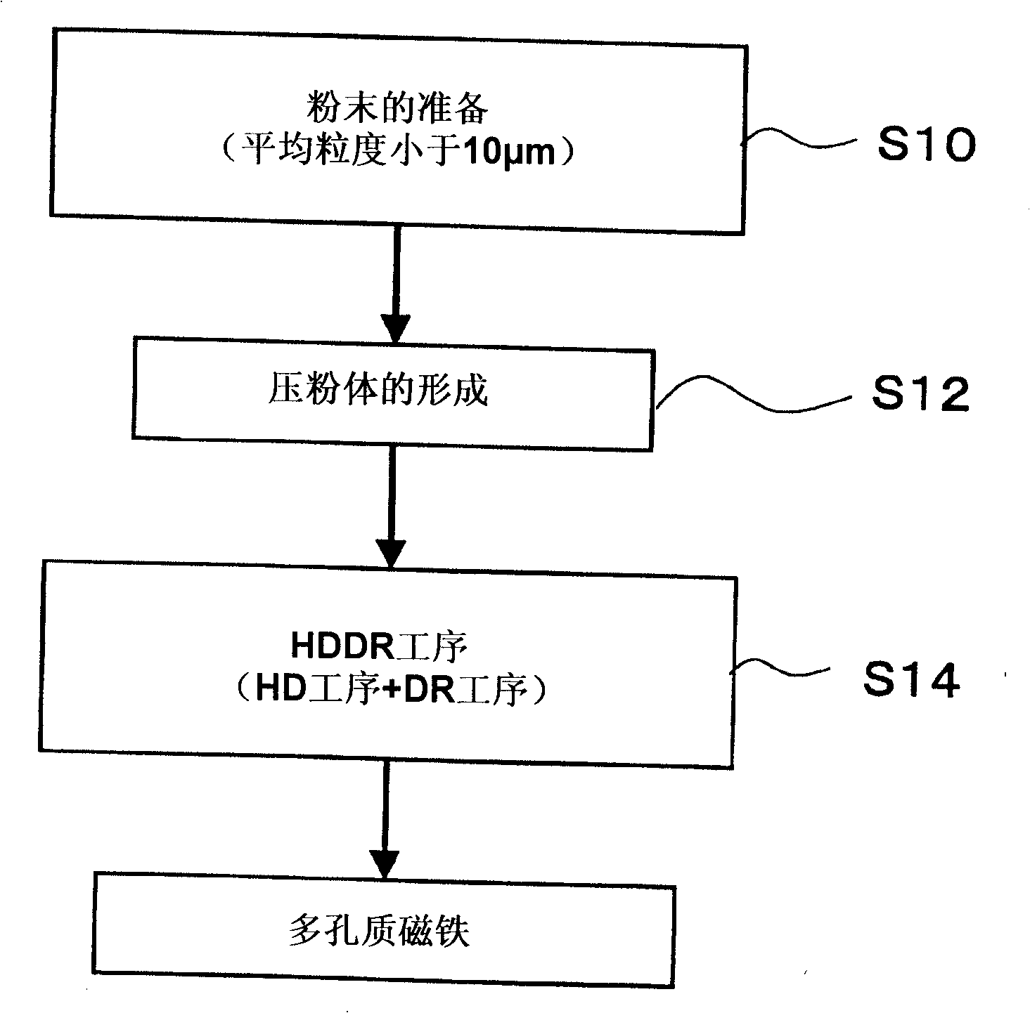
[0113] Hereinafter, preferred embodiments of the method for producing the R—Fe—B based porous magnet of the present invention will be described in detail.
[0115] First, an ingot of an R-T-Q-based alloy (starting alloy) having an R-Fe-B phase as a hard magnetic phase is prepared. Here, "R" is a rare earth element including Nd and / or Pr at 50 atomic % (at%) or more. The rare earth element R in this specification also includes yttrium (Y). "T" is at least one transition metal element selected from Fe, Co, and Ni, and is a transition metal element including 50% or more of Fe. "Q" is B, or a combination of B and a portion of B replaced by C.
[0116] The R-T-Q type alloy (starting alloy) includes Nd with a volume ratio of 50% or more 2 Fe 14 Type B compound phase (hereinafter abbreviated as "R 2 T 14 Q").
[0117] Most of the rare earth element R included in the starting alloy is composed of R 2 T 14 Q, but partly also constituted as R 2 o 3 W...
Embodiment 1
[0224] An alloy (target composition: Nd 13.65 Fe bal co 16 B 6.5 Ga 0.5 Zr 0.09 (atomic %)), a porous rare earth permanent magnet was produced by the production method of the above-mentioned embodiment. The unit of the numerical value in Table 1 is mass %. Hereinafter, the production method of this embodiment will be described.
[0225] [Table 1]
[0226] Alloy
Nd
Pr
Fe
co
B
Ga
Zr
A
29.7
0.1
remnant
14.3
1.06
0.50
0.13
[0227] First, a rapidly solidified alloy having a composition shown in Table 1 was produced by a strip casting method. The obtained rapidly solidified alloy was coarsely pulverized into a powder having a particle diameter of 425 μm or less by a hydrogen storage and collapse method, and then finely pulverized using a jet mill to obtain a fine powder with an average particle diameter of 4.4 μm. Moreover, the "average particle diamet...
Embodiment 2
[0244] Next, the porous magnet of Example 1 was pulverized with a mortar in an argon atmosphere, and classified to produce a powder having a particle diameter of 75 to 300 μm. This powder was put into a cylindrical container, oriented in a magnetic field of 800 kA / m, and fixed with paraffin. After the obtained sample was magnetized in a pulsed magnetic field of 4.8 MA / m, magnetic properties were measured with a vibrating sample type fluxmeter (VSM: device name VSM5 (manufactured by Toei Kogyo Co., Ltd.)). Also, no diamagnetic field correction is performed. The measurement results are shown in Table 3.
[0245] [table 3]
[0246] Alloy
J max
(T)
B r
(T)
h cB
(kA / m)
(BH) max
(kJ / m 3 )
h cJ
(kA / m)
h k
(kA / m)
A
1.16
1.14
595
203
864
338
[0247] J in the table max and B r The true density of the sample is 7.6g / cm 3 obt...
PUM
| Property | Measurement | Unit |
|---|---|---|
| Crystal particle size | aaaaa | aaaaa |
| Long trail | aaaaa | aaaaa |
| Particle size | aaaaa | aaaaa |
Abstract
Description
Claims
Application Information