
Condensed water circulating cooling energy-conserving and emission-cutting technology

A water cycle cooling, energy-saving and emission-reducing technology, applied in energy-saving heating/cooling, steam engine installation, climate sustainability, etc., can solve the problems of loss of precious water resources, waste of low-temperature heat energy, environmental heat pollution, etc., and achieve environmental protection and social benefits Significantly, the effect of reducing coal consumption for power generation and reducing pollution

Inactive Publication Date: 2009-02-04
张贵祥
View PDF0 Cites 7 Cited by
  • Summary
  • Abstract
  • Description
  • Claims
  • Application Information

AI Technical Summary

Problems solved by technology

[0003] The circulating water cooling tower, a landmark building in a thermal power plant, swallows clouds and mist all the year round, and most of the heat is discharged into the atmosphere through the cooling tower. pollution, but also increased SO 2 , CO 2 , smoke, dust, and ash emissions pollute the environment, and ultra-supercritical units with higher power generation efficiency are less than 50%, while general medium-temperature, medium-pressure and high-temperature and high-pressure power generation efficiencies are only 24.5% and 30.5% respectively, and the loss rate of heat energy is high. The utilization rate of water does not exceed 40%. It can be seen that the key to energy saving and emission reduction of thermal power plants lies in the recovery and utilization of waste heat. The potential economic, social and environmental benefits are huge.

Method used


Image

  • Condensed water circulating cooling energy-conserving and emission-cutting technology
  • Condensed water circulating cooling energy-conserving and emission-cutting technology
  • Condensed water circulating cooling energy-conserving and emission-cutting technology

Examples


Embodiment Construction

[0020] Take the drawings as an example to further describe the present invention

[0021] figure 1 , figure 2 , image 3 , Figure 4 , Figure 5 It is a process flow diagram of an embodiment of the present invention

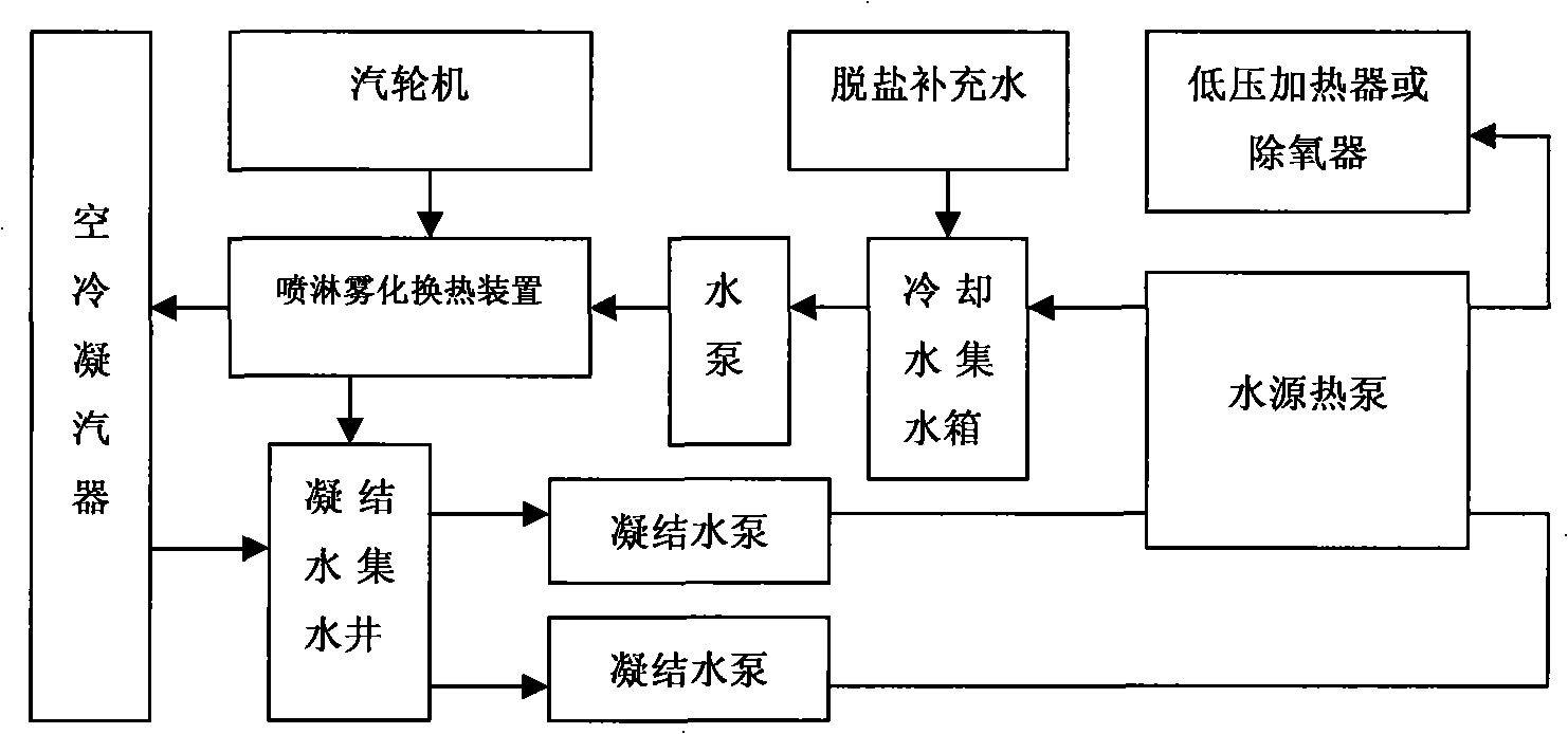
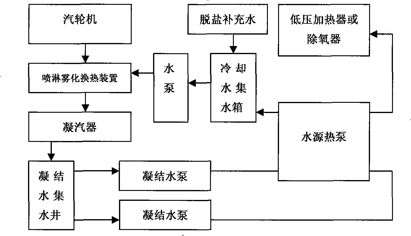
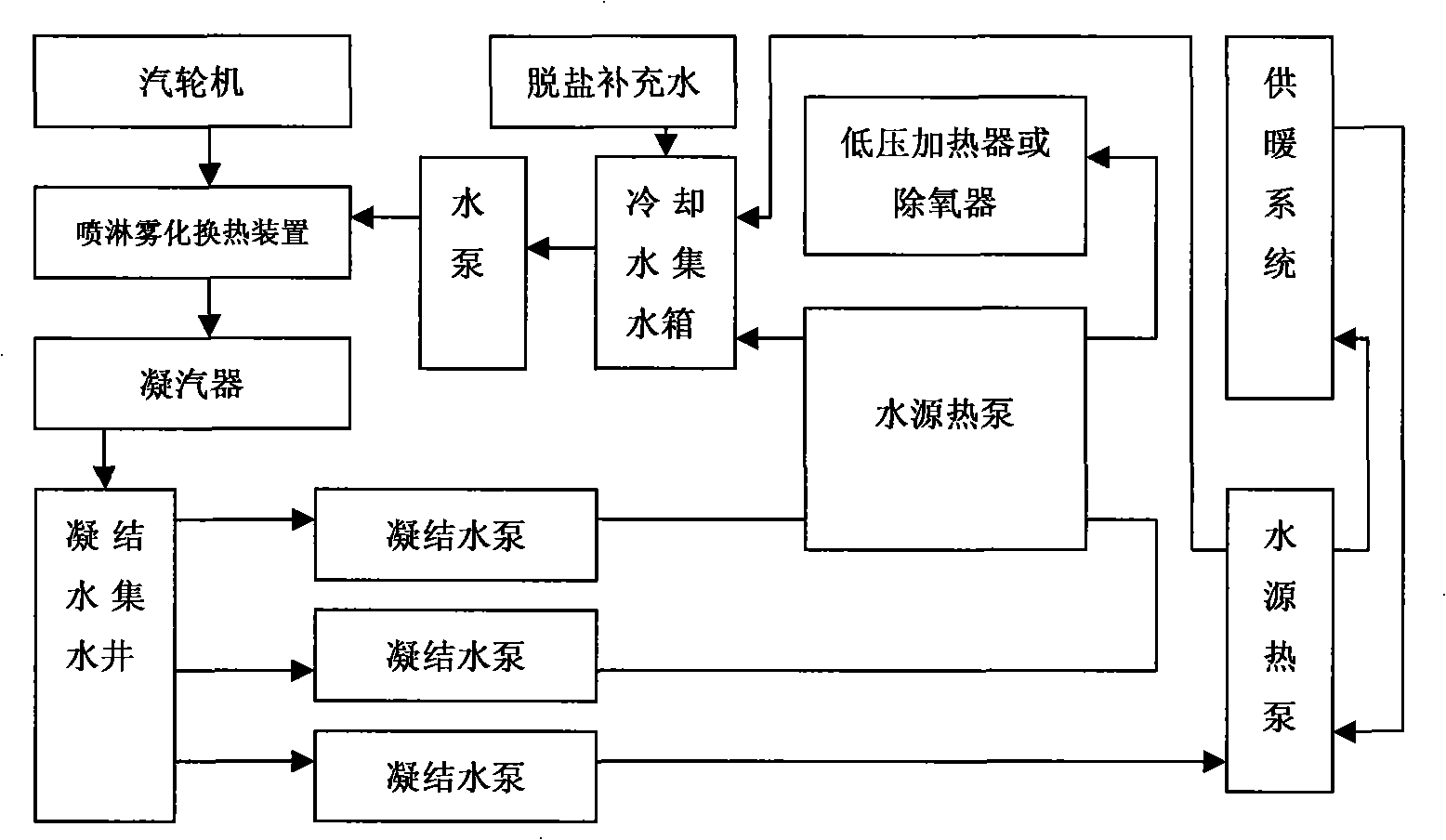
[0022] Condensate circulating cooling energy saving and emission reduction technology (such as figure 1 , figure 2 , image 3 , Figure 4 (Shown), at the high temperature end of the steam turbine exhaust pipe, the condensed water spray atomized steam water is directly mixed and condensed by heat exchange. The condensate after heat exchange and condensation flows into the condensate collection well, and is sent to the water source heat pump by the condensate pump through the water source After the heat pump is refrigerated, it is sent back to the high temperature end of the exhaust pipe to spray and atomize to form a cooling cycle. At the same time, the water source heat pump converts the waste heat to boiler feed water of the same water quality or heating and oth...


PUM


Abstract

The invention discloses a condensate water circulation cooling energy-saving emission-reduction technology. Condensate water as well as sprayed and atomized steam water are adopted to be directly mixed with heat exchange condensation at a high temperature end in the exhaust orifice of a steam turbine; the condensate water after heat exchange condensation flows into a condensate water collection well, is pumped into the hot pump of a water source by a condensate water pump, returned to the high temperature end in the exhaust orifice for spraying and atomizing to form cooling circulation after being cooled by the hot pump of the water source; the afterheat is transferred to a boiler simultaneously when being cooled by the hot pump of the water source to form afterheat circulation for the water consumption of water or other different water qualities. The technology has a plurality of functions of energy saving, water saving, environment protection, running cost reducing, efficiency improving, etc. The technology realizes the cooling circulation and afterheat circulation in particular and gains new breakthrough on the aspects of improving the heat exchange effect, increasing the vacuity of a machine set, improving the output, the afterheat recycling and utilizing as well as energy saving and emission reducting; besides, the environment protection and the social benefit are remarkable.

Description

Technical field [0001] The invention relates to a condensed water circulating cooling energy saving and emission reduction technology, which is mainly used in the field of thermal power. Background technique [0002] Lack of water resources, energy depletion and serious environmental pollution are common phenomena at present. Water, energy and environmental issues in the 21st century are issues of universal concern to the world. In recent years, with the rapid development of modern science and technology, people pay more and more attention to the low-temperature heat energy that has not been effectively used until now. Among the low-temperature heat energy that has not been effectively used, the low-temperature heat energy of thermal power plants is one of them. [0003] Circulating water cooling towers in the iconic buildings of thermal power plants swallow clouds and fog all the year round, and most of the heat is discharged into the atmosphere through the cooling towers. This ...

Claims


Application Information

Patent Timeline
IPC IPC(8): F01K19/00F22D1/50
CPCY02B30/52Y02B30/123
Inventor 张贵祥张文峰索敬云
Owner 张贵祥
Learn More