Rotating micro-example auto-introducing device

An introduction device, rotary technology, applied in the field of microfluidic analysis, to achieve the effect of low consumption, reliable performance and good application prospects

Inactive Publication Date: 2012-03-14
NORTHEASTERN UNIV LIAONING
View PDF0 Cites 1 Cited by
  • Summary
  • Abstract
  • Description
  • Claims
  • Application Information

AI Technical Summary

Problems solved by technology

[0004] Aiming at the problems existing in the existing sample introduction technology, the present invention provides a rotary micro-sample automatic introduction device

Method used


Image

  • Rotating micro-example auto-introducing device
  • Rotating micro-example auto-introducing device
  • Rotating micro-example auto-introducing device

Examples


Embodiment 1

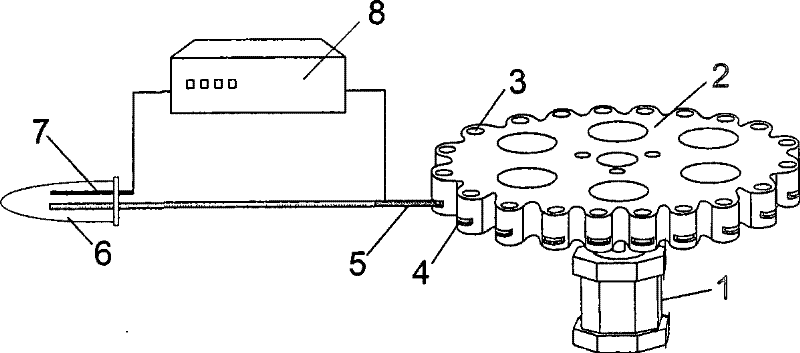
[0023] Rotary micro-sample automatic introduction device such as figure 1 As shown, the integrated sample tray 2 is gear-shaped, with a diameter of 7 cm and a thickness of 8 cm. There are 20 barrel-shaped liquid storage pools 3 evenly distributed on the edge. The inner diameter of each liquid storage pool 3 is 3.5 mm, and the depth is 7 mm. On the same horizontal plane, and each liquid storage pool 3 is evenly distributed on the integrated sample plate 2, the minimum distance between the side of the plate body and the inner wall of the liquid storage pool is 2 mm, and each liquid storage pool 3 has a same shape and the same cross-sectional area at the bottom of the outer side The pores 4 are 1.2mm in width and 2.0mm in depth. Each pore 4 connects the inside of the liquid storage tank with the outside of the integrated sample tray 2 and is on the same horizontal plane; the integrated sample tray 2 is fixed on the stepping motor 1 axis, concentric with the axis of stepper motor ...

Embodiment 2

[0032] The integrated sample tray 2 of the rotary micro-sample automatic introduction device is gear-shaped, with a diameter of 1cm and a thickness of 0.1cm. There are barrel-shaped liquid storage pools evenly distributed on the edge. The inner diameter of each liquid storage pool is 0.5mm and the depth is 2mm. , the bottom surface is on the same level, and the reservoirs are evenly distributed on the integrated sample tray, the minimum distance between the side of the tray and the inner wall of the reservoir is 2mm, and the outer bottom of each reservoir has the same shape and the same cross-sectional area pore, the pore width is 0.5mm, and the depth is 2.0mm. Each pore connects the inside of the liquid storage tank with the outside of the integrated sample plate, and is on the same horizontal plane; the integrated sample plate is fixed on the shaft of the stepping motor, and The shafts of the stepper motors are concentric.

[0033] The capillary sampling probe is a fused sil...

Embodiment 3

[0036] The integrated sample tray 2 of the rotary micro-sample automatic introduction device is gear-shaped, with a diameter of 100 cm and a thickness of 10 cm. There are 500 barrel-shaped liquid storage pools evenly distributed on the edge. The inner diameter of each liquid storage pool is 5 mm and the depth is 50 mm. The bottom surface is on the same level, and the reservoirs are evenly distributed on the integrated sample tray. The minimum distance between the side of the tray and the inner wall of the reservoir is 5mm. There is a hole with the same shape and the same cross-sectional area at the bottom of each reservoir. Pore, the width of the pore is 0.5mm, and the depth is 5mm. Each pore connects the inside of the liquid storage tank with the outside of the integrated sample plate, and is on the same horizontal plane; the integrated sample plate is fixed on the shaft of the stepping motor, and the The shaft of the motor is concentric.

[0037] The capillary sampling probe...


PUM

PropertyMeasurementUnit
thicknessaaaaaaaaaa
diameteraaaaaaaaaa
thicknessaaaaaaaaaa

Abstract

The invention relates to a rotary type micro-sample automatic leading-in device which comprises an integral sample tray, a capillary sampling probe, a step motor, a high-voltage power supply, an electrode, and a liquid storage pipe and is characterized in that the integral sample tray takes a shape of gear, specifically, liquid storage pools are evenly distributed on the outer edge of the circular tray body, and each of the liquid storage pools is opened with a hole; the outer wall of the sample inlet end of the capillary sampling probe is plated with a metal layer or a plurality of metal layers and the sample inlet end can be inserted into the hole of a liquid storage pool of the integral sample tray. When the integral sample tray rotates, the probe does not contact the body of the integral sample tray. The invention can realize automatic sample introduction and change without using any pump or valve, with the time of sample change being less than 0.2s and the rate of consumption of the sample solution being nL grade, thus the automatic leading-in device can be adopted as a high-throughput sample leading-in device for relevant analytical instruments.

Description

technical field [0001] The invention belongs to the technical field of microfluidic analysis, in particular to a rotary automatic micro sample introduction device. Background technique [0002] Microfluidic analysis is a frontier field of analytical chemistry developed in the early 1990s. It is based on analytical chemistry and supported by micro-electromechanical processing technology. The goal is to integrate the functions of the entire laboratory on a microchip and build a chip. The laboratory realizes the overall miniaturization, automation, integration and portability of various analysis systems. Microfluidic chip capillary electrophoresis is one of the fastest-growing fields in microfluidic analysis. It has the advantages of fast separation, easy parallel operation, automation, integration, and low cost. However, for a high-throughput, automated microfluidic analysis system, a suitable sample introduction interface is very important, which is also one of the bottlenec...

Claims


Application Information

Patent Timeline
Patent Type & Authority Patents(China)
IPC IPC(8): G01N35/08G01N21/64
Inventor 徐章润樊晓峰裴晓华陈志新方肇伦
Owner NORTHEASTERN UNIV LIAONING
Why Eureka
Try Eureka