Laser scribing dust collector and operation method thereof

A technology of dust removal device and laser engraving, which is used in fine work devices, work accessories, stone processing equipment, etc., can solve the problems of low dust removal efficiency, aging wiring, noise pollution, etc., and achieve high dust removal efficiency, accelerated aging, and consumption. Can less effect

Inactive Publication Date: 2009-04-08
东莞宏威薄膜真空技术有限公司
View PDF0 Cites 16 Cited by
  • Summary
  • Abstract
  • Description
  • Claims
  • Application Information

AI Technical Summary

Problems solved by technology

[0004] Using the above-mentioned first high-power exhaust fan closed environment drainage method to collect and process the dust generated during the marking process has certain effects on the surface film of small-area amorphous silicon solar panels and low-speed marking lines, but for such as amorphous silicon When the thin-film solar panel film substrate is a large-area glass score line of 1100 mm × 1400 mm, the dust cannot be completely absorbed, resulting in low dust removal efficiency. On the one hand, it is difficult to form a large closed space to generate sufficient airflow; on the other hand On the one hand, a high-power exhaust fan must be introduced to realize the function of dust removal, and a high-power exhaust fan will cause greater noise pollution and increase energy consumption. At the same time, it is not easy to dissipate heat in a closed space, and the long-term high-temperature environment will accelerate wiring. aging and shorten the life of the motor, resulting in increased costs and potential safety hazards
[0005] Using the above-mentioned second full-coverage air collection box dust removal method, due to the large wind direction inlet area, the air flow in the entire

Method used


Image

  • Laser scribing dust collector and operation method thereof

Examples


Example Embodiment

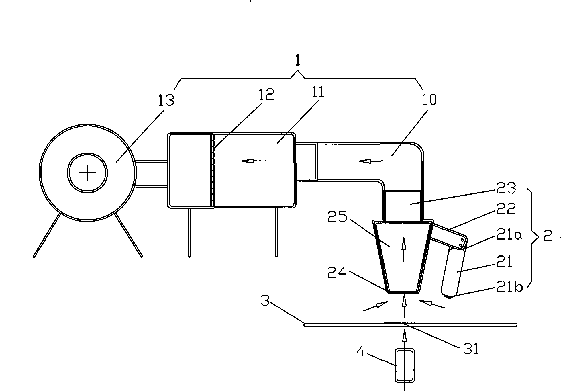
[0019] Such as figure 1 As shown, the laser scoring dust removal device of the present invention is applied to the laser generator 4 to remove dust when the amorphous silicon solar panel 3 is scribed. The laser scoring dust removal device includes a dust suction device 1 and a suction device 2. The device 1 is connected to the exhaust device 2. The exhaust device 2 includes an exhaust box 25 and a static elimination rod 21 connected to the outside thereof. The exhaust box 2 has an exhaust box air inlet 24 and an exhaust box air outlet 23. The suction box air outlet 23 is in communication with the dust suction device 1, and the suction box air inlet 24 covers directly above the engraved track 31 of the amorphous silicon solar panel 3; the air suction box air inlet 24 covers and The dust can be effectively absorbed on the top of the engraved track, and the exhaust system provided by the low-power dust removal device can effectively absorb the dust, reducing energy consumption and no...


PUM


Abstract

The invention discloses a laser marking dust remover, which is suitable for removing dust when a laser generator marks an amorphous silicon solar panel. The laser marking dust remover comprises a dust suction device and a ventilator, wherein the dust suction device is communicated with the ventilator; the ventilator comprises an exhaust chamber and an electrostatic removal rod which is connected to the outside of the exhaust chamber; the exhaust chamber is provided with an exhaust chamber air inlet and an exhaust chamber air outlet which is communicated with the dust suction device; and the exhaust chamber air inlet is directly over a marking track of the amorphous silicon solar panel by means of covering. The laser marking dust remover sucks dust pertinently by utilization of the exhaust chamber set, can widen the dust removal range and improve the pertinency to the utmost degree by matching the exhaust chamber set and the electrostatic removal rod, has a simple structure and low cost, can obtain ideal dust removal effect by utilization of an exhaust fan with small power, does not need a closed environment, and can have the function of temperature reduction when mixing the dust into drainage gas. Moreover, the invention also discloses a method for operating the laser marking dust remover.

Description

technical field [0001] The invention relates to a dedusting device for cleaning and collecting dust, in particular to a laser dedusting device for dedusting when a laser generator is used to dedust an amorphous silicon solar panel. Background technique [0002] In the process of preparing solar panels, especially in the process of preparing amorphous silicon solar panels, every evaporation (or sputtering, or coating) needs to be laser scribed with a laser generator. The dust generated during the scribing process, the dust will be deposited on the scribing groove and the board, and the above-mentioned dust will be covered in the next evaporation (or sputtering, or coating) process, which will cause the layout of the board to occur. Short circuit; at the same time, the dust deposited on the glass surface will also affect the film thickness and uniformity in the next evaporation process, thereby reducing the photoelectric conversion rate of the entire board. [0003] At presen...

Claims


Application Information

Patent Timeline
IPC IPC(8): B28D7/02B28D5/04
Inventor 覃海王勇蓝劾
Owner 东莞宏威薄膜真空技术有限公司
Why Eureka
Try Eureka