

Method for preparing manganese sulfate solution by using sulphur dioxide gas leach manganese dioxide ore
A manganese sulfate solution, sulfur dioxide technology, applied in manganese sulfate and other directions, can solve the problems of affecting the absorption rate of sulfur dioxide, large volume flow, waste of sulfur resources, etc., and achieve continuous, stable and high-efficiency production, low grade requirements, and high utilization rate Effect
- Summary
- Abstract
- Description
- Claims
- Application Information
AI Technical Summary
Problems solved by technology
Method used
Image

Examples
Embodiment
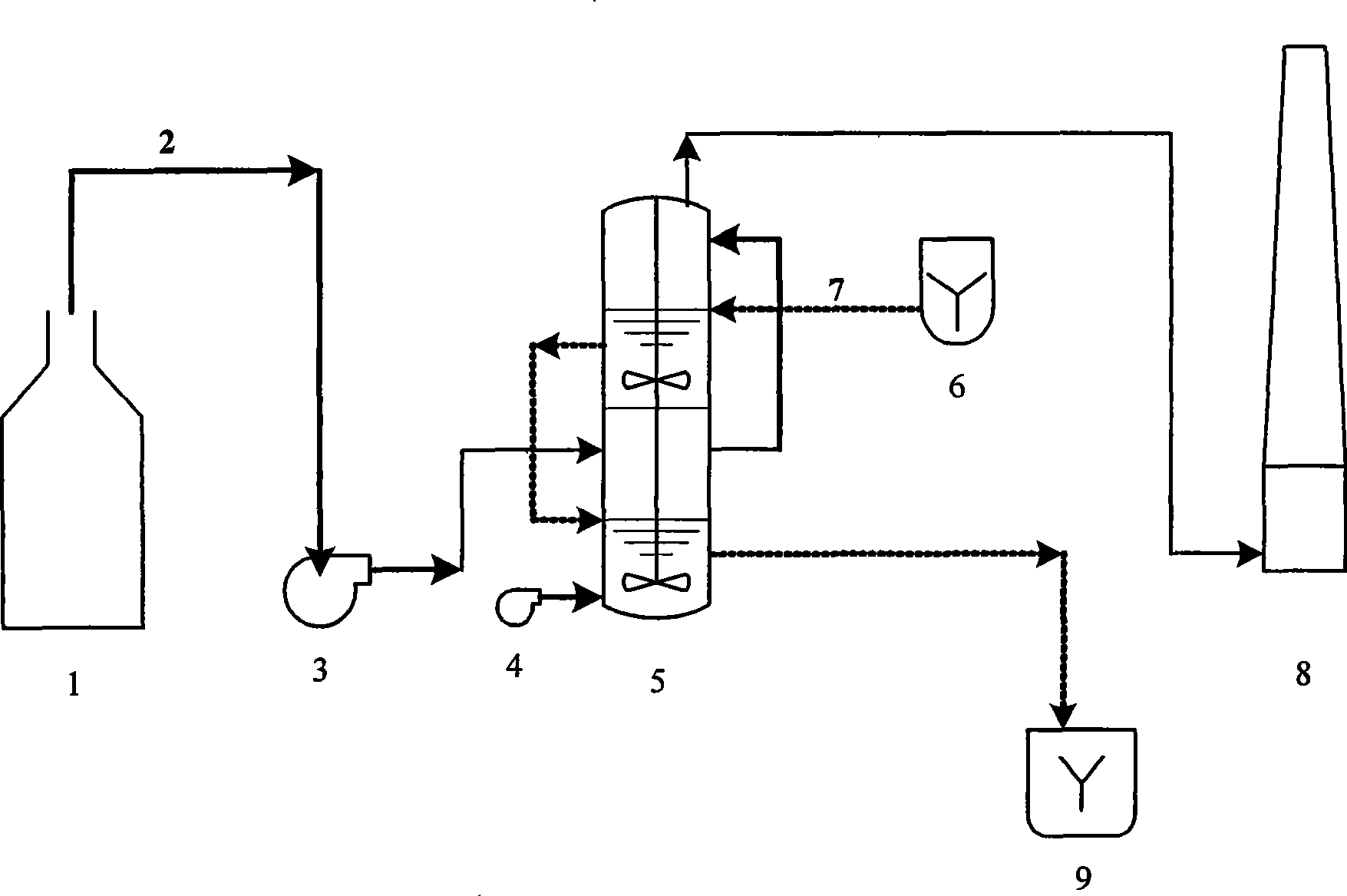
[0051] In this embodiment, the reactor 5 is a device comprising two-stage absorption and leaching reaction chambers arranged in series up and down directly connected by pipelines. Sulfur dioxide gas comes from sulfur roasting generation system 1, and the sulfur dioxide gas production is 6000Nm 3 / h, after cooling down to about 80°C through heat exchange, it is sent into the absorption reactor 5 by the blower 3 through the pipeline 2 at a pressure of 8000Pa. Pyrolulurite with a particle size of less than 100 mesh and water are prepared in the pulp tank 6 equipped with agitator to make a pulp with a liquid-solid ratio (mass ratio) of 2:1, and then sent to the absorption reactor 5 through the pulp pipeline 7 by a pump. Oxygen is sent into the absorption reactor 5 by the blower 4 . In the reactor, sulfur dioxide gas and oxygen are continuously sent into the second-stage absorption and leaching reaction chamber of the reactor respectively, and enter the pulp that overflows and des...
PUM
 Abstract
Description
Claims
Application Information