Coal powder entrance structure applied to reactor for producing acetylene with plasma coal cracking

A technology of plasma and reactor, applied in the direction of organic chemistry, etc., to alleviate the phenomenon, increase the yield of acetylene, and alleviate the effects of coking

Inactive Publication Date: 2009-08-19
TSINGHUA UNIV +1
View PDF3 Cites 13 Cited by
  • Summary
  • Abstract
  • Description
  • Claims
  • Application Information

AI Technical Summary

Problems solved by technology

Since the research on the production of acetylene by high-power plasma coal cracking is in its infancy, reports on the structure design of its pulverized coal inlet are seldom published in public literature

Method used


Image

  • Coal powder entrance structure applied to reactor for producing acetylene with plasma coal cracking
  • Coal powder entrance structure applied to reactor for producing acetylene with plasma coal cracking
  • Coal powder entrance structure applied to reactor for producing acetylene with plasma coal cracking

Examples


Embodiment 1

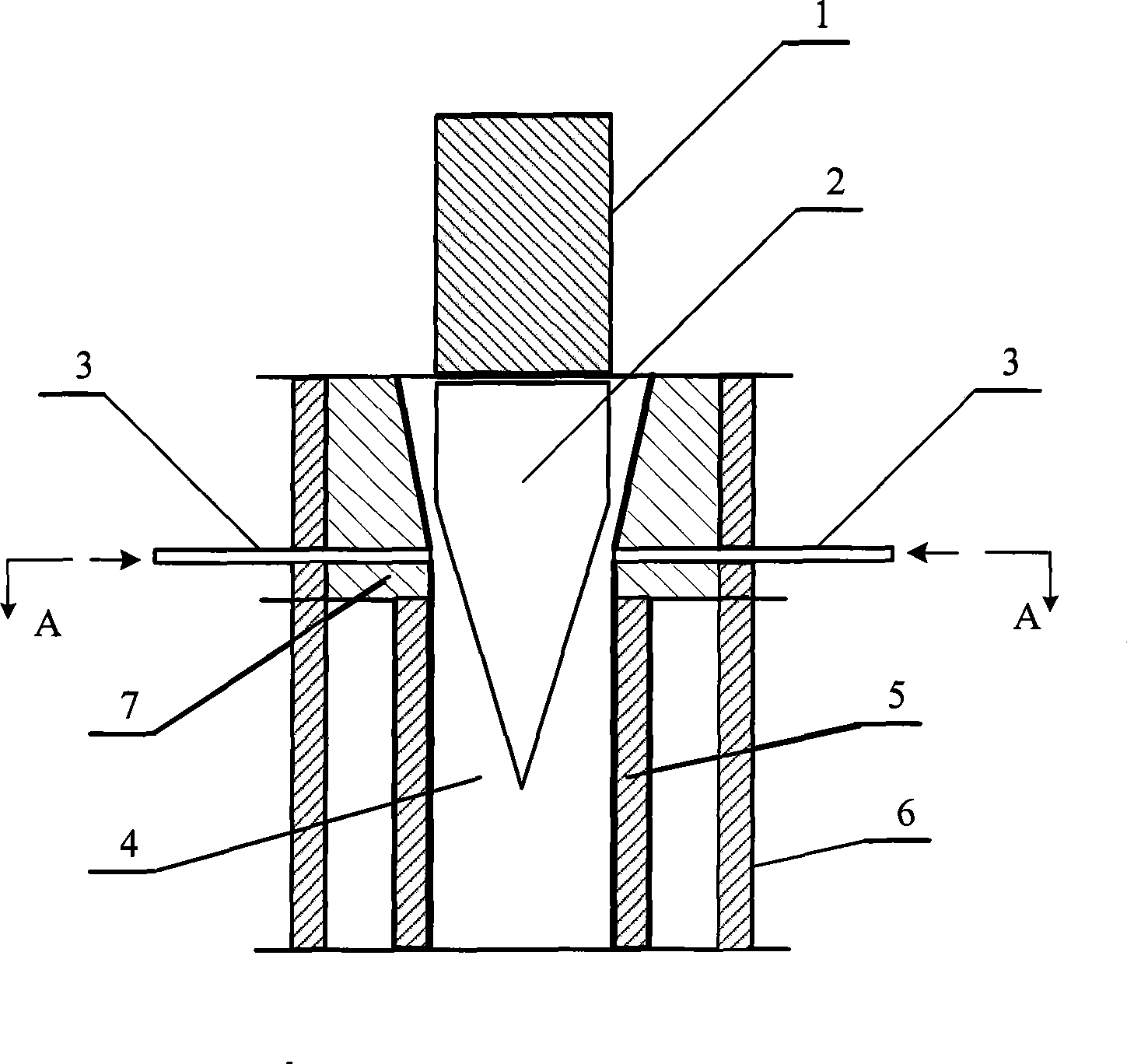
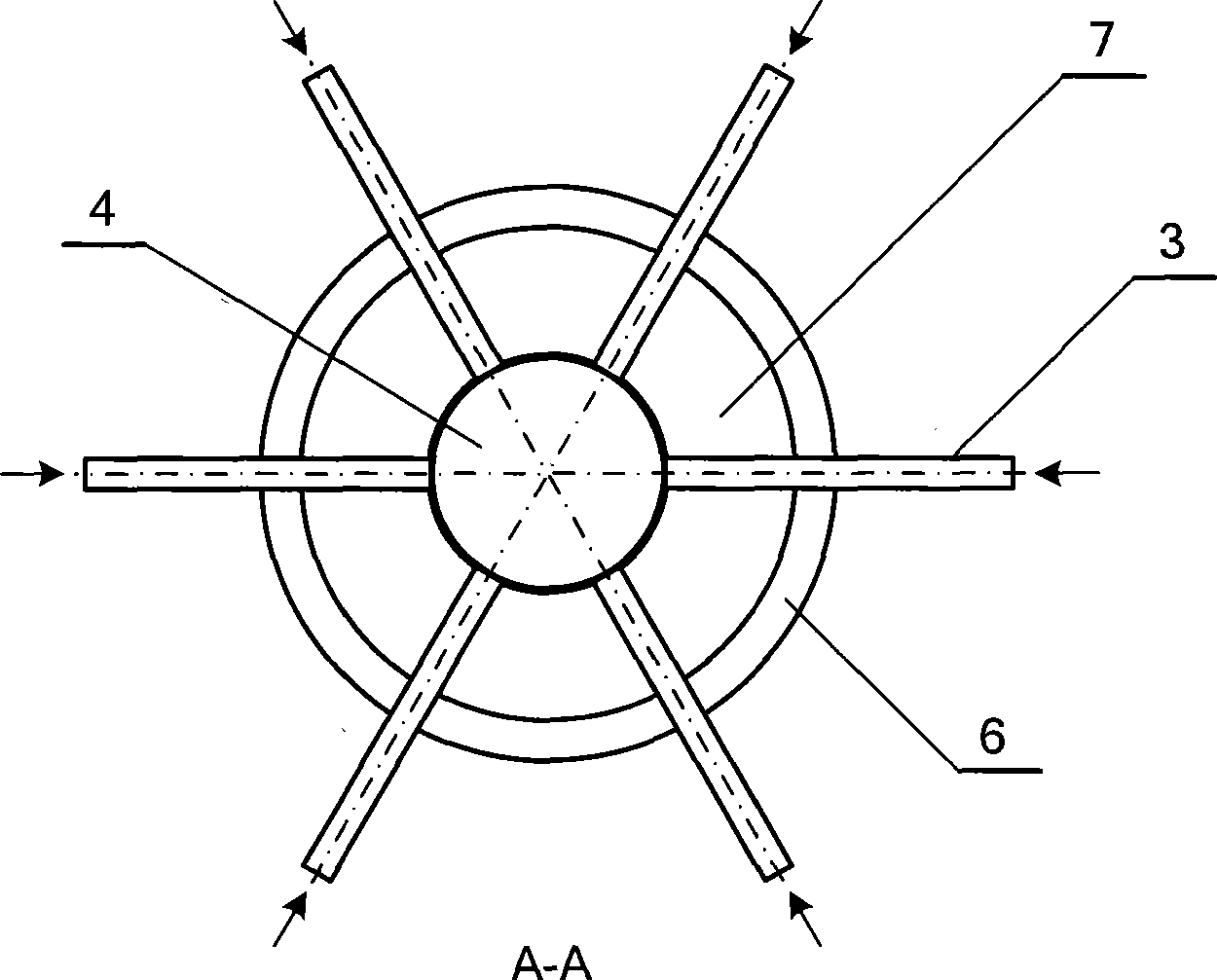
[0027] figure 1 It is a device schematic diagram of the present invention, a pulverized coal inlet structure applied to a reactor for producing acetylene by plasma coal cracking, including a plasma generator 1, a gas-solid down-bed reactor channel 4, an inner wall 7 of the reactor channel, and an outer wall 6, The graphite inner wall 5 and the pulverized coal nozzle 3 located below the plasma generator 1 and surrounding the thermal plasma jet 2 in the channel 4 of the gas-solid down-bed reactor, the pulverized coal inlet structure is as follows Figure 6 Shown in (a) and (b), the number of pulverized coal nozzles 3 is 6, and the outlet cross-section of pulverized coal nozzles 3 is wide and flat, and is a rectangle with a length of 15.6 mm and an aspect ratio of 6 ( image 3 Several typical wide and flat pulverized coal nozzle cross-sections are provided), the ratio of the 1 / 2 power of the cross-sectional perimeter P to the cross-sectional area A is 5.72, and the major axis 9 o...

Embodiment 2

[0030] A pulverized coal inlet structure applied to a reactor for producing acetylene by plasma coal cracking, comprising a plasma generator 1, a gas-solid down-bed reactor channel 4) an inner wall 7 of the reactor channel, an outer wall 6, a graphite inner wall 5 and a plasma Below the generator 1, around the pulverized coal nozzle 3 surrounding the thermal plasma jet 2 in the channel 4 of the gas-solid down-bed reactor, the pulverized coal inlet structure is as follows: Figure 6 As shown in (c) and (d), the number of pulverized coal nozzles 3 is 6, and the outlet cross-section of pulverized coal nozzles 3 is wide and flat, which is an ellipse with a major axis of 16.2mm and a ratio of major to minor axes of 6. The ratio of P to the 1 / 2 power of the cross-sectional area A is 5.82, and the major axis 9 (major axis of the ellipse) of the outlet cross-section of the pulverized coal nozzle (3) and the cross-section 8 of the reactor channel 4 have an angle α, α It is 0 °, and the...


PUM


Abstract

The invention discloses a coal dust inlet structure applied to preparing an acetylene reactor by plasma coal pyrolysis, belonging to the technical field of industrial gas-solid two-phase mixing and reacting efficiently and rapidly. The outlet cross section of the coal dust spray head of the inlet structure is wide and flat; a long axis of the outlet cross section of the coal dust spray head forms a cut angle alpha with the cross section of the reactor channel; the coal dust spray heads are in central symmetrical distribution at the inner wall of the reactor channel; tangent of intersection of circumference surface of the cross section of the reactor channel inner wall where the coal dust spray heads are arranged and central line of the coal dust spray head forms an angle beta with the central line of the coal dust spray head; the central line of the coal dust spray head forms a cut angle gamma with the cross section of the reactor channel. The invention provides a coal dust inlet structure applied to preparing the acetylene reactor by plasma coal pyrolysis; by the structure, the coal dust sprayed by the coal dust spray heads can be well mixed with high temperature plasma jet, thereby effectively improving yield of acetylene and lessening coking of the reactor.

Description

technical field [0001] The invention belongs to the technical field of high-efficiency and rapid mixing and reaction of industrial gas-solid two-phase, and particularly relates to a pulverized coal inlet structure applied to a reactor for producing acetylene by plasma coal cracking. Background technique [0002] Acetylene is an important basic organic chemical raw material. The industrial methods for producing acetylene mainly include calcium carbide method, methane partial oxidation method and methane arc cracking method. Among them, the calcium carbide method acetylene process is mature and accounts for an absolute proportion in industrial production, but the pollution and energy consumption are relatively high. Plasma pyrolysis of coal to acetylene is a new and promising route for direct chemical conversion of coal. Since the 1990s, Chinese scholars and engineering technicians have carried out a lot of basic research and engineering research in this field. Because my co...

Claims


Application Information

Patent Timeline
Patent Type & Authority Applications(China)
IPC IPC(8): C07C11/24
Inventor 程易陈家琦郭文康熊新阳黄峥嵘吴昌宁周军
Owner TSINGHUA UNIV
Why Eureka
Try Eureka