
Resonance micro electromechanical system magnetic field sensor and measuring method thereof

A technology of micro-electromechanical systems and magnetic field sensors, which is applied in chemical instruments and methods, the size/direction of magnetic fields, and components of TV systems, etc. It can solve the problems of high power consumption, high manufacturing process requirements, and complex structures of comb resonators. problems, to achieve the effect of reliable electrical contact, high sensitivity, high precision and high sensitivity

Inactive Publication Date: 2009-08-26
SOUTHEAST UNIV
View PDF0 Cites 22 Cited by
  • Summary
  • Abstract
  • Description
  • Claims
  • Application Information

AI Technical Summary

Problems solved by technology

These magnetic field sensors can only measure the magnitude of the magnetic field. In addition, a comb tooth magnetic field sensor deflects the comb teeth through the interaction between the permanent magnet and the magnetic field to measure the direction of the magnetic field, but this structure processing technology is not a standard CMOS process. , the structure is complex, the manufacturing process is demanding, and the power consumption required to make the comb resonator move is relatively large

Method used


Image

  • Resonance micro electromechanical system magnetic field sensor and measuring method thereof
  • Resonance micro electromechanical system magnetic field sensor and measuring method thereof
  • Resonance micro electromechanical system magnetic field sensor and measuring method thereof

Examples


Embodiment 1

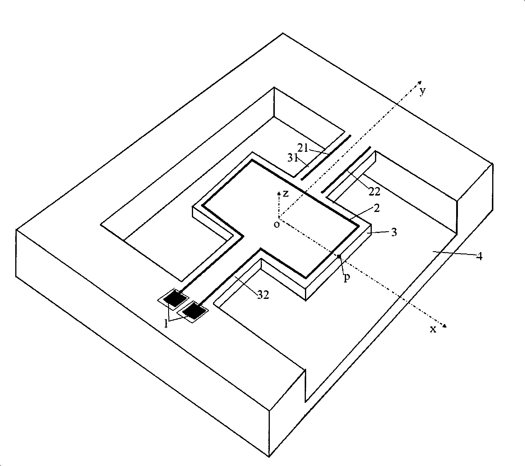
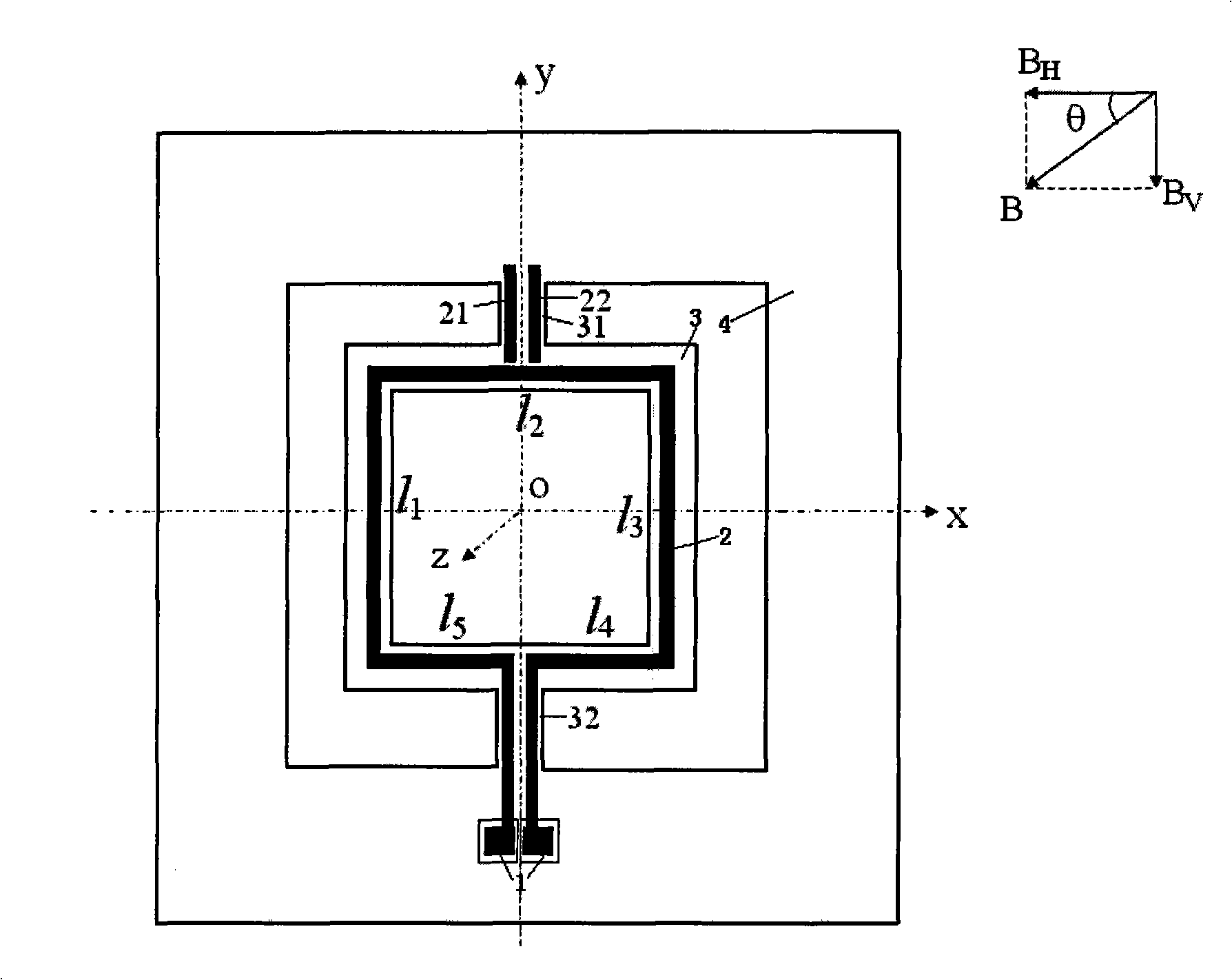
[0052] A resonant MEMS magnetic field sensor includes a substrate 4, a cantilever plate 3 and metal wires 2, the cantilever plate 3 is arranged on the substrate 4 in parallel, and the metal wire 2 is arranged on the cantilever plate 3. The metal wire 2 may be made of Al, Au, etc., and the metal wire 2 and the anchor region 1 are obtained by etching. The metal wire 2 drives the suspension wall plate 3 to vibrate, and the amplitude of the vibration depends on the magnitude of the current applied to the metal wire 2 and the strength of the magnetic field.

[0053] In this embodiment, the metal wires 2 can be plated on the upper surface of the cantilever plate 3 by evaporation or electroplating, and the metal wires can also be arranged on the above positions by sputtering. When the cantilever plate is vibrated by magnetic force excitation, an insulating layer needs to be provided between the metal wire 2 and the cantilever plate 3 . The material of the metal wire 2 can be aluminu...

Embodiment 2

[0057] The invention is a resonant micro-electromechanical system magnetic field sensor for measuring the direction of a magnetic field, which is composed of an anchor area 1 , an induction metal wire 2 , a cantilever plate 3 and a substrate 4 . The sensor takes the substrate 4 as the plane, on the substrate 4 is provided a sensor structure composed of metal wires 2, cantilever plates 3, and anchor regions 1, which are left and right symmetrical to the center line, and the metal wires 2 drive the cantilever plates 3 to vibrate.

[0058] After the structure is completed, firstly, under the known magnitude and direction of the magnetic field, an alternating current is passed on the metal wire 2 respectively. The displacement at the second order frequency is used to calibrate k 1 / Q 1 and k 2 / Q 2 The value of , as a parameter fixed to the structure.

[0059] When measuring, first place the magnetic field sensor in the magnetic field to be measured, and then pass alternating ...


PUM


Abstract

The invention relates to a resonance micro electromechanical system magnetic field sensor and a measuring method thereof, having the advantages of low power consumption, simple structure, rapid respondency and good reliability. The magnetic field sensor comprises an anchorage (1), a metal wire (2), a contilever plate (3) and a substrate (4). The metal wire (2) plated on the contilever plate (3) drives the contilever plate (3) under the action of lorentz force to generate vibration; excitation is respectively used for producing resonance having the same excitation frequency as first order and second order of the contilever plate; when the first order and the second order are in resonance, the structure has the directions with the difference of 90 degrees; the different displacements of a p point are measured by measuring the displacement of the p point on the contilever plate after the magnetic field directions of the first order and the second order are changed, thus the measurement of the magnetic field directions can be realized. The invention aims at providing a micro electromechanical system magnetic field sensor which has low power consumption, high sensitivity and precision and simple structure, and is seldom influenced by temperature.

Description

technical field [0001] The invention relates to a resonant micro-electromechanical system magnetic field sensor and its measurement method. The principle is that the structure has different motion forms when it moves in different modes, so it measures the displacement generated when different modes move, and realizes the measurement of the direction of the magnetic field. It belongs to sensors Design technology field. Specifically, the magnetic field sensor with a plate structure has different motion forms in different modes, and the magnetic field force related to the magnetic field direction produces different motion forms. This structure adopts a process compatible with CMOS (Complementary Metal-oxide Semiconductor), which can Achieve monolithic integration of excitation and detection circuits. [0002] The object of the present invention is to provide a MEMS magnetic field sensor with low power consumption, high sensitivity, high precision and little influence by temperat...

Claims


Application Information

Patent Timeline
IPC IPC(8): G01R33/02B81B7/02B81C5/00B81C99/00
Inventor 陈洁黄庆安秦明李成章
Owner SOUTHEAST UNIV
Learn More