Dewatered sludge endless grate incinerator

A technology of chain grate and incineration device, which is applied to incinerators, combustion methods, combustion types, etc., can solve the problem that flue gas and fly ash are difficult to achieve harmless, fly ash cannot be harmless, and it is difficult to achieve harmless and other problems, to achieve the effect of long flue gas residence time, reducing flue gas flow area, and ensuring harmlessness

Inactive Publication Date: 2009-09-23
陈宝林
View PDF7 Cites 1 Cited by
  • Summary
  • Abstract
  • Description
  • Claims
  • Application Information

AI Technical Summary

Problems solved by technology

It is difficult for the existing incineration technologies to fully meet these two stringent requirements. Relatively speaking, the fire chamber combustion method (powdered coal furnace) can achieve a high furnace outlet smoke temperature, but the amount of fly ash powder is more than 90%. The ash cannot be harmless; the flue gas temperature at the furnace outlet of the circulating fluidized bed combustion method is lower than that of the pulverized coal furnace, and the amount of fly ash powder is more than 70%, and it is difficult to achieve harmless flue gas and fly ash; the bubbling fluidized bed The flue gas temperature at the furnace outlet is low, and the amount of fly ash powder is greater than 50%. Although the ash stays for a long time and the ash can be completely harmless, it is difficult for the flue gas and fly ash to be harmless; the fire bed combustion method, especially the chain Grate, with the smallest proportion of fly ash and a very long residence time of ash among all combustion plants, is therefore most suitable as a sludge incineration plant

Method used


Image

  • Dewatered sludge endless grate incinerator

Examples


Embodiment Construction

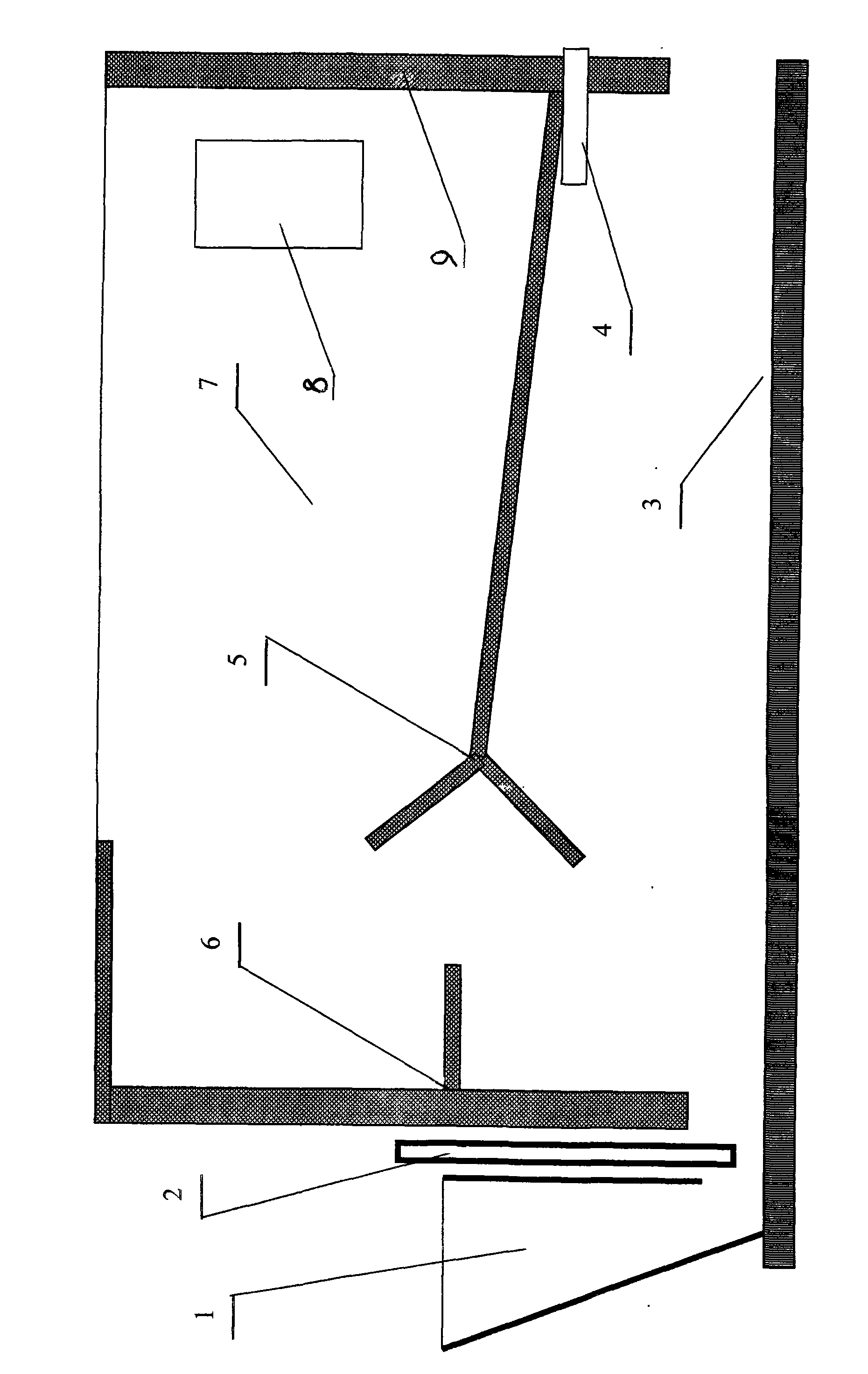
[0014] like figure 1 As shown, a chain grate incinerator with a processing capacity of 1 ton per hour of dried sludge includes a furnace, coal scuttle, coal gate, chain grate, grate air, and secondary air system. The length of chain fire grate 3 is 3 meters, and the fire grate width is 2 meters. A front arch 6 with an F-shaped longitudinal section and a rear arch 5 with a horizontal Y-shaped longitudinal section are arranged in the hearth above the chain grate. The horizontal projection length of the back arch is 2 meters. The lower branches of the back arch are inclined backwards with an inclination angle of 30 degrees; the upper branches are inclined with an inclination angle of 60 degrees. The vertical section of the F-shaped front arch is the front wall of the furnace, and the upper branch of the horizontal section is close to the furnace roof, and the vertical distance from the grate surface is 2200mm. The lower branch of the horizontal section is located between the up...


PUM


Abstract

A dewatered sludge endless grate incinerator belongs to the technical field of hazardous waste incineration equipment. The invention aims at providing a dewatered sludge endless grate incinerator with a small amount of flying ash and high furnace exit fume temperature. The technical key points are as follows: a furnace above an endless grate (3) is internally provided with a front arch (6) with F-shaped longitudinal section and a rear arch (5) with horizontally Y-shaped longitudinal section and the two arches are mutually matched; an upper branch on the horizontal segment of the F-shaped front arch closely clings to the furnace top and a lower branch on the horizontal segment is positioned between an upper branch and a lower branch of the horizontally Y-shaped rear arch; the space between the outlet of the rear arch and the front arch forms a main combustion area; a nozzle of an air channel (4) of a secondary air system is arranged at the rear part of the rear arch by attaching to the wall; and a radiation cooling chamber (7) is arranged between the furnace outlet and an outlet smokestack (8) . The incinerator realizes the two basic conditions for complete decontamination by incinerating harmful solid waste under high temperature: extremely small amount of flying ash and extremely high furnace exit smoke temperature, has simple structure, easy operation and is an ideal facility for incinerating harmful wastes.

Description

technical field [0001] The invention relates to an incineration device for hazardous waste, in particular to a device for incinerating sludge in a fire bed furnace. Background technique [0002] Hazardous solid waste, such as various garbage and sludge, can completely kill bacteria and viruses after high-temperature incineration, and eliminate harmful substances such as odorous substances, dioxins, and polycyclic aromatic hydrocarbons including benzopyrene , At the same time, the heavy metal components can be fully solidified (high temperature sintering can greatly reduce the amount of heavy metals that can be dissolved in water), so high temperature incineration is an effective means of completely harmless solid waste. [0003] Direct blending in existing coal-fired devices is the lowest-cost method of wet sludge incineration. For wet sludge with high water content, the water evaporates and absorbs a lot of heat, and the theoretical combustion temperature is extremely low....

Claims


Application Information

Patent Timeline
Patent Type & Authority Applications(China)
IPC IPC(8): F23G7/00
Inventor 宋振林宋渝曹磊
Owner 陈宝林
Why Eureka
Try Eureka