Thermal power plant combined ventilation direct air cooling system

A technology for thermal power plants and air cooling systems, which is applied in steam/steam condensers, lighting and heating equipment, tubular elements, etc., and can solve problems such as the fluctuation of the cooling efficiency of the condenser, the fluctuation of the steam turbine, the high distance of the equipment from the ground, and the impact on the heat dissipation efficiency. Achieving the effect of optimizing the technical approach

Active Publication Date: 2009-10-07
孙丽
View PDF0 Cites 20 Cited by
  • Summary
  • Abstract
  • Description
  • Claims
  • Application Information

AI Technical Summary

Problems solved by technology

Since each condenser unit is very large, for example, the diameter of the fan is usually 9 meters, and the erection height is often as high as tens of meters. For a 600,000-kilowatt generating set, 64 sets of condenser units are required to condense the steam. Therefore, the direct air-cooling system in a thermal power plant needs to occupy a huge space, and the high-rise condenser unit and its cooling fan also bring great difficulties to the daily maintenance of the equipment
[0003] In addition, the condenser unit in the existing direct air cooling system is directly installed outdoors, and is greatly affected by environmental factors such as external temperature, wind direction, and wind speed during operation.
When the ambient temperature is high, the cooling efficiency of the condenser is low, and when the ambient temperature is low, the cooling efficiency of the condenser is high. In this way, direct air cooling is used in areas with a large temperature difference between day and night, which will cause large fluctuations in the work of the steam turbine in the power plant, which will affect power generation. The stable power generation of the plant
Similarly, the wind direction and wind speed will also affect the cooling efficiency of the condenser and cause fluctuations in the operation of the steam turbine, resulting in instability of the power generation of the power plant
[0004] In addition, the surface of the finned tube bundle of the condenser exposed to the air is easy to accumulate dust, which affects its effective heat dissipation.
[0005] Problems in the ventilation mode of the air-cooled island: 1. The operation is not stable due to the strong influence of the wind; 2. The phenomenon of hot air backflow is relatively serious; 3. The energy consumption of the fan is high; It is easy to accumulate dust, which affects the heat dissipation efficiency
5. In the case of sunshine, the exposed condenser fin tube bundle absorbs the sun's radiant heat, and the heat carried away by the heated air through the condenser fin tube bundle contains the sun's radiant heat, thereby reducing the heat dissipation efficiency
6. The equipment is high from the ground, making maintenance and cleaning difficult
[0006] When the above problems are mild, they will increase the coal consumption of power generation and affect the stable power generation. In severe cases, the unit will trip and affect the operation of the power grid.

Method used


Image

  • Thermal power plant combined ventilation direct air cooling system
  • Thermal power plant combined ventilation direct air cooling system
  • Thermal power plant combined ventilation direct air cooling system

Examples


Embodiment 1

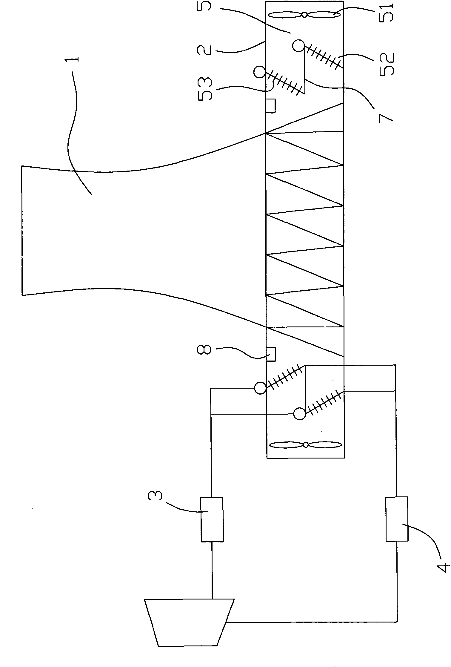
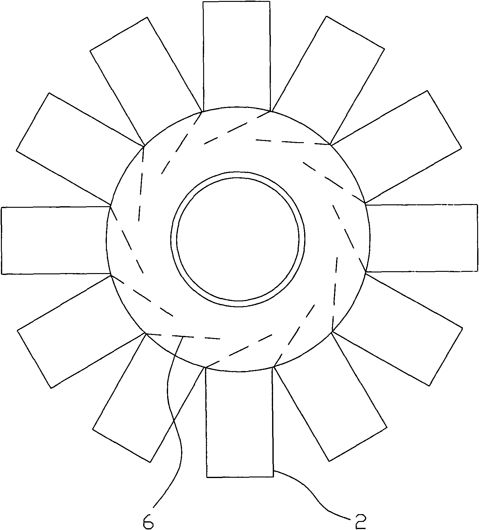
[0027] Such as figure 2 As shown, the combined ventilation direct air cooling system of the thermal power plant of the present invention comprises a hyperbolic air cooling tower 1, the outside of the bottom of the air cooling tower 1 is densely covered with several air inlet passages 2 along its circumference, and the air inlet passages 2 are cylindrical structures. The air passage 2 can be made of a square pipe, the outer end of the air inlet passage 2 is open, the inner end of the air inlet passage 2 communicates with the inside of the air cooling tower 1, and each air inlet passage 2 is provided with an air condenser unit 5 . The air condenser unit 5 includes an axial fan 51 and a heat dissipation fin tube bundle 52 , and the axial flow fan 51 and the heat dissipation fin tube bundle 52 are arranged along the axis of the air inlet channel 2 . A cooling fin cleaning device 8 is also arranged in the air inlet channel 2 .

[0028] The axial flow fan 51 in the air condenser u...

Embodiment 2

[0039] Such as Figure 5 As shown, in order to meet the working requirements of different climates and different regions, the outside of the bottom of the air cooling tower 1 of the present invention can be provided with multiple layers of the air inlet channel along the height direction. In this embodiment, upper and lower layers of air inlet channel 9 and air inlet channel 10 are arranged. The structures of the air inlet channel 9 and the air inlet channel 10 , internally connected devices, externally connected devices, etc. are all in common with those in the first embodiment. In order to form the helical exhaust air flow in the air cooling tower 1, two sets of corresponding structures have been designed in the present embodiment: 1) as Figure 6 As shown, in the cooling tower 1, a deflector with an included angle with the radial line of the air cooling tower 1 is provided, and each air inlet channel is correspondingly provided with a deflector; 2) as Figure 7 As shown, ...


PUM


Abstract

The present invention disclose a thermal power plant combined ventilation direct air cooling system, including hyperbolic air cooling tower, a plurality of air intake channels arranged along the circumferential direction on outboard of the air cooling tower bottom, and the air intake channel is cylandrical structure of open outer end and inner end communicated with the air cooling tower internal, inside each air intake channel is arranged with air condensator unit connected with steam turbine exhaust pipe and condensation water collecting pipe, outside air exchange heat with the air condensator unit in the air intake channel and expel from the air cooling tower. The invention sets air intake channel and the matching hyperbolic air cooling tower, and makes full use of pumping action of the air cooling tower to airflow in the premise of assuring fan activity, greatly reduce the affect if ambient wind velocity, wind direction, temperature and assure reliable and stable cooling to the heat dissipating finned tube, and provide guarantee to power generating plant stable power generation. The invention provides a feasible, optimized technology approach for present thermal power plant alteration.

Description

technical field [0001] The invention relates to the technical field of thermal power plant cooling, in particular to a combined ventilation direct air cooling system. Background technique [0002] The direct air cooling system is one of the cooling methods for the steam exhausted from the steam turbine in the existing thermal power plant. The steam discharged from the steam turbine is sent to the finned tube bundle of the air-cooled condenser arranged outdoors through the exhaust pipe, and the cooling air flows outside the finned tube to condense the exhaust steam in the tube, and the condensed water obtained is sent to the heating system for recycling. Such as figure 1 As shown, the direct air cooling system usually consists of several condenser units, and each condenser unit is composed of a finned tube bundle and a large-diameter axial flow fan. Below the finned tube bundle, the finned tube bundle is directly air-cooled by a fan (also known as the air-cooled island vent...

Claims


Application Information

Patent Timeline
Patent Type & Authority Applications(China)
IPC IPC(8): F28B1/06F28B9/08F28F9/22F28F1/24F28F13/12
Inventor 姜宗林郝德麟刘杰克
Owner 孙丽
Why Eureka
Try Eureka