Optical pickup, optical disc device, compound coupling lens, compound prism and optical information apparatus
A technology of coupling lenses and pickups, applied in beam guides, information storage, optical recording heads, etc., can solve the problems of no display countermeasures, biased focus error signals, and reduced performance of optical discs.
- Summary
- Abstract
- Description
- Claims
- Application Information
AI Technical Summary
Problems solved by technology
Method used
Image
Examples
Embodiment approach 1
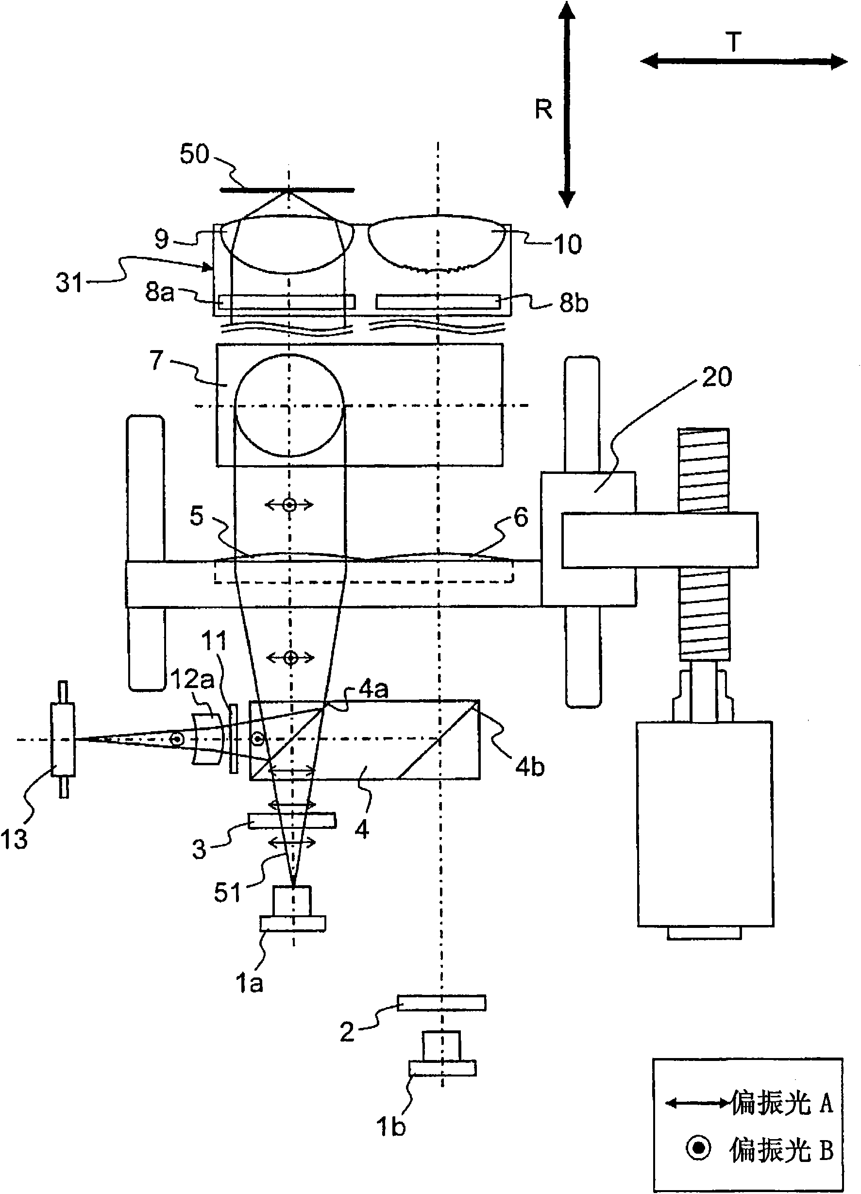
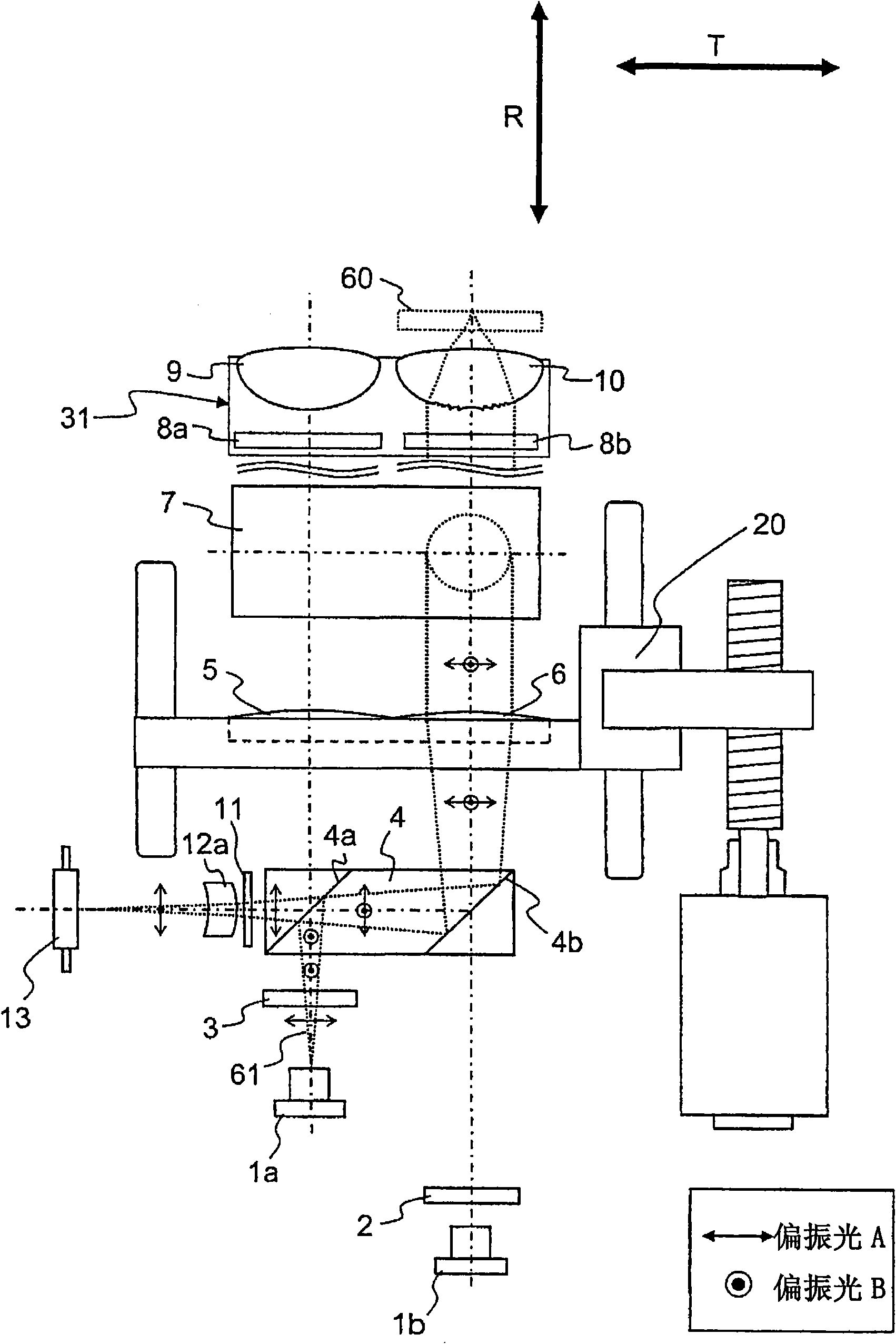
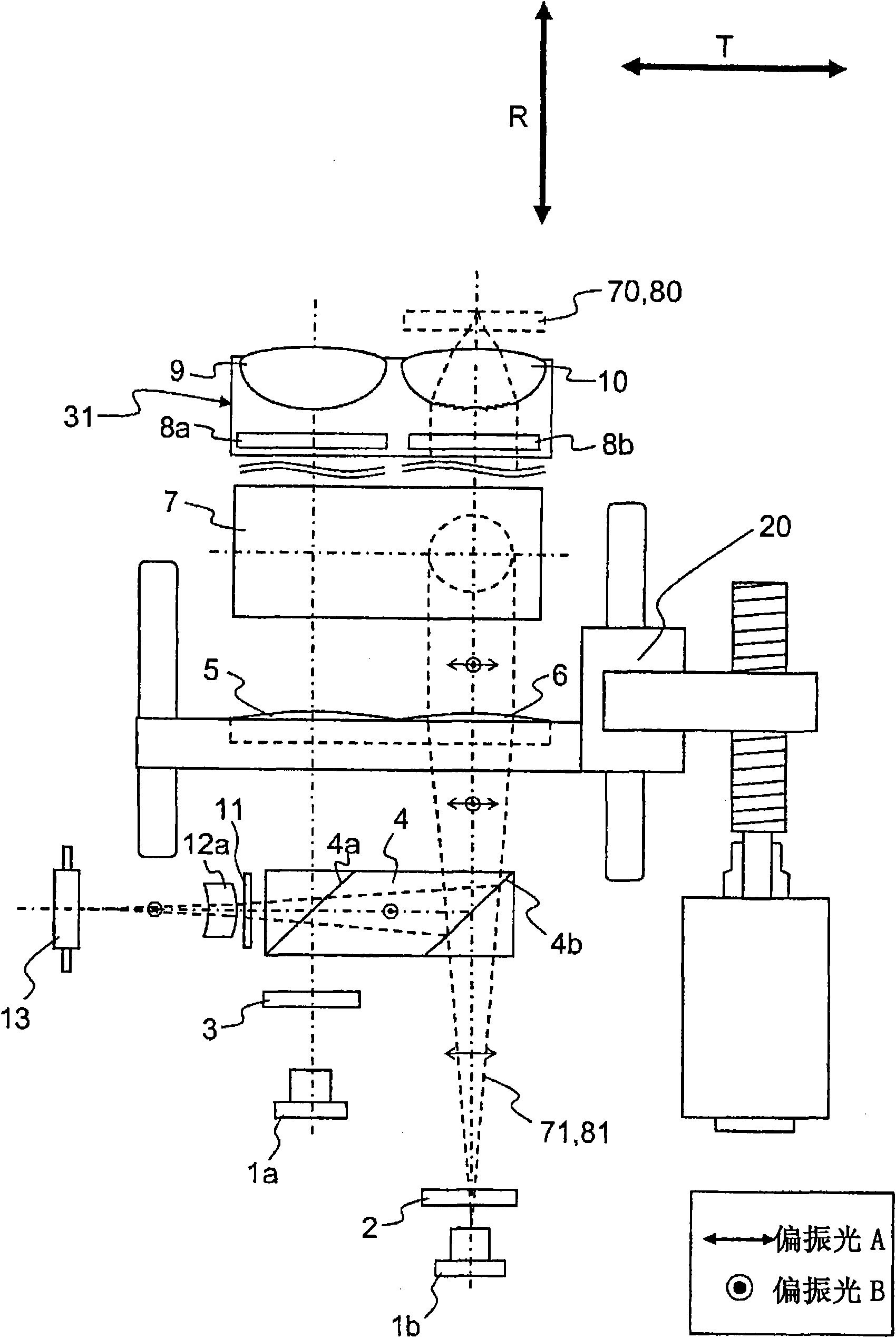
[0319] figure 1 , figure 2 and image 3 is a schematic configuration diagram of an optical pickup according to an embodiment of the present invention. in addition, Figure 1 to Figure 3 The main building blocks of the optical pickup shown are shown by the block diagram in Figure 30 and Figure 31 middle. Figure 30 The shown optical pick-up uses a kind of laser light with wavelength λ1, and can carry out the interaction between the first information recording medium (also called medium) 50 in the form of an optical disc and the second information recording medium 60 in the form of an optical disc. Replace the optical pickup used. in addition, Figure 31 The optical pickup shown can still be used interchangeably with the first information recording medium 50 formed in the form of an optical disc and the second, third, and fourth information recording media 60, 70, and 80 formed in the form of an optical disc. optical pickups such as Figure 31 The shown process gene...
Embodiment approach 2
[0420] Figure 15 , Figure 16 , Figure 17 , Figure 18 and Figure 19 It is a schematic configuration diagram of an optical pickup according to an embodiment of the present invention.
[0421] exist Figure 15 ~ Figure 19 In , components having the same functions as those in Embodiment 1 are assigned the same symbols and their descriptions are omitted. In the optical pickup of the first embodiment described above, the polygonal prism 4 has the first optical surface 4a and the second optical surface 4b, but in the optical pickup of the second embodiment, on the polygonal prism 4, except for the first optical surface 4a It has the 3rd optical surface 4c other than the 2nd optical surface 4b. The optical surface 4c is the third optical surface of the polygonal prism 4, which has the spectral characteristics of substantially totally transmitting the blue-violet light beams and substantially totally reflecting the red and infrared light beams. In addition, in this embodime...
Embodiment approach 3
[0457] Figure 44 , Figure 45 and Figure 46 It is a schematic configuration diagram of an optical pickup according to an embodiment of the present invention.
[0458] exist Figure 44 , Figure 45 , Figure 46 Among them, 1001a is a first light source emitting blue-violet laser light corresponding to the first laser light, and 1001b is a second light source emitting laser light of two wavelengths, red laser light corresponding to the second laser light and infrared laser light corresponding to the third laser light.
[0459] 1002 is a dichroic prism, 1003 is a diffraction grating, 1004 is an outgoing collimator lens equivalent to an outgoing coupling lens, 1005 is a polarized light conversion element composed of a liquid crystal or a transparent piezoelectric element, and 1006 is equivalent to realizing optical path switching In the polarizing beam splitter as an example of the function of the prism, 1008 is a standing mirror, 1009a and 1009b are 1 / 4 wavelength plates, ...
PUM
 Abstract
Description
Claims
Application Information
 - R&D
- Intellectual Property
- Life Sciences
- Materials
- Tech Scout
- Unparalleled Data Quality
- Higher Quality Content
- 60% Fewer Hallucinations
Browse by: Latest US Patents, China's latest patents, Technical Efficacy Thesaurus, Application Domain, Technology Topic, Popular Technical Reports.
© 2025 PatSnap. All rights reserved.Legal|Privacy policy|Modern Slavery Act Transparency Statement|Sitemap|About US| Contact US: help@patsnap.com


