Process for heat treatment of amorphous transformer core

A technology of heat treatment furnace and process, which is applied in the direction of heat treatment furnace, inductor/transformer/magnet manufacturing, heat treatment equipment, etc. It can solve the problems of increasing grain size and deteriorating magnetic properties of strips, and achieves reduced loss, good magnetic properties, high Effect of flux value

Inactive Publication Date: 2009-11-11
TONGJI UNIV
View PDF0 Cites 22 Cited by
  • Summary
  • Abstract
  • Description
  • Claims
  • Application Information

AI Technical Summary

Problems solved by technology

The αFe phase produced by the primary crystallization, especially the uniform nanoscale αFe phase grains, can greatly improve the magnetic properties of the amorphous strip; however, the secondary crystallization will greatly increase the grain size, which will deteriorate the magnetic properties of the strip. can

Method used


Image

  • Process for heat treatment of amorphous transformer core
  • Process for heat treatment of amorphous transformer core

Examples


Embodiment 1

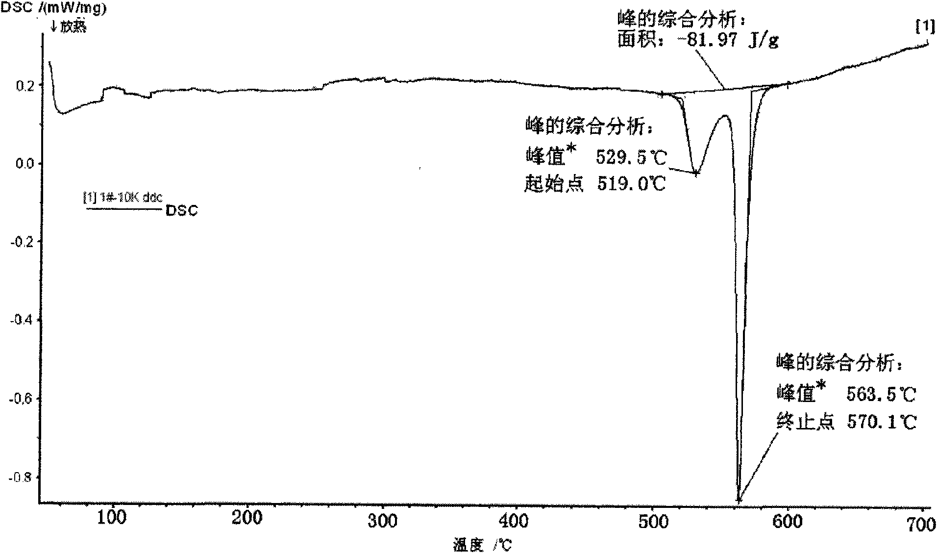
[0024] Such as figure 1 As shown in the DSC curve of a typical amorphous strip, it can be seen that the amorphous has a crystallization peak at 750K and 830K respectively. When heated to around 750K, the crystal phase begins to form inside the isotropic amorphous phase, primary crystallization begins when it exceeds 750K, and secondary crystallization begins when it reaches 830K. The αFe phase produced by primary crystallization, especially the uniform nanoscale αFe phase grains, greatly improves the magnetic properties of the amorphous strip. The secondary crystallization will greatly increase the size of the grains but will deteriorate the magnetic properties of the strip.

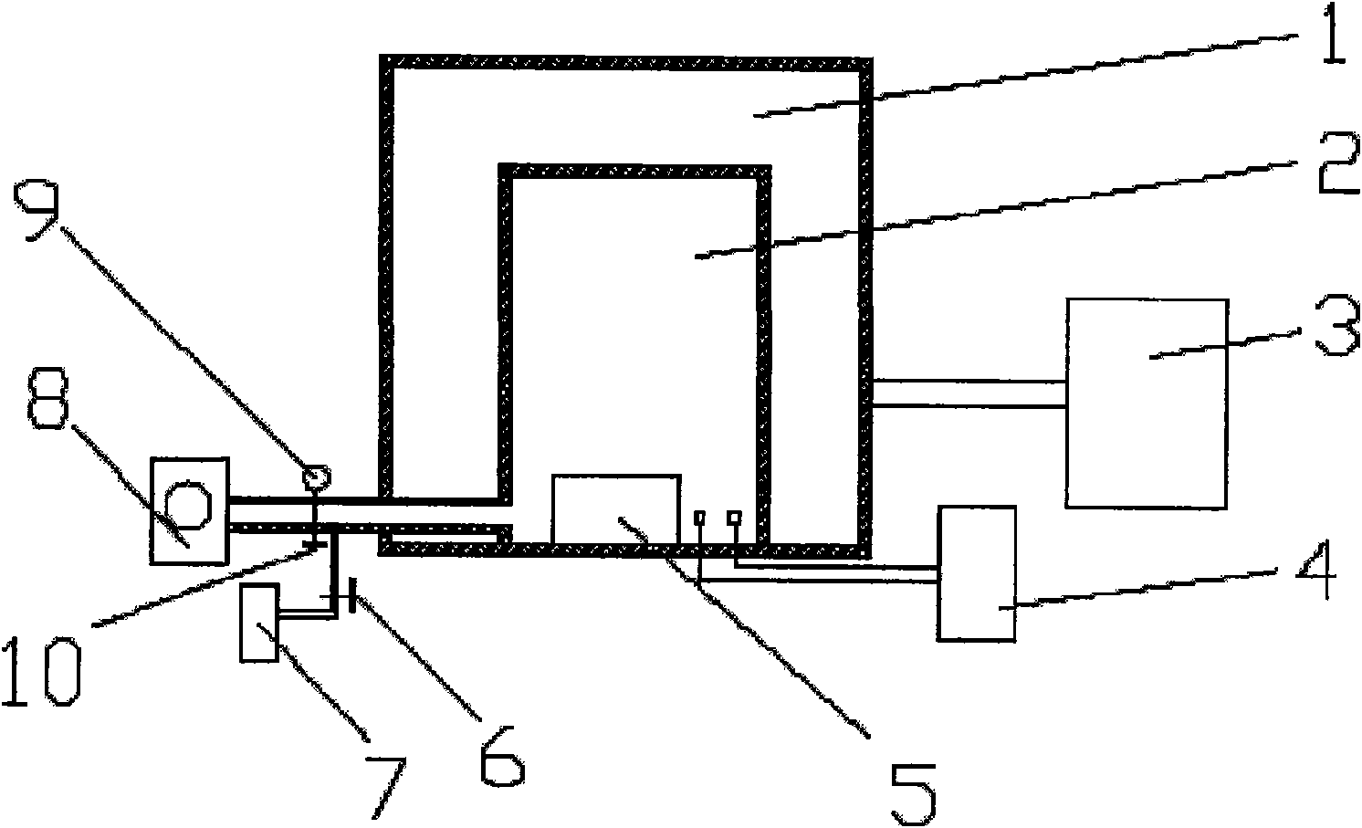
[0025] Such as figure 2 The shown heat treatment furnace is composed of heat treatment furnace heating chamber 1, heat treatment furnace vacuum chamber 2, heating temperature control device 3, magnetizing equipment 4, stage 5, nitrogen bottle 7, vacuum pump 8 and pressure gauge 9, wherein: heat treatm...

Embodiment 2

[0031] Put the wound domestic amorphous iron core into the vacuum chamber 2 of the heat treatment furnace, wind 6 turns of 10mm in diameter enamelled insulated thick copper wire, and cover the furnace cover. Open the valve 10 and the vacuum pump 8, stop the vacuum pump 8 when the vacuum reaches -0.1MPa, and close the valve 10 leading to the vacuum pump 8. Open valve 6 and nitrogen bottle 7 afterwards, charge nitrogen, until nitrogen pressure is 0.5MPa, then close nitrogen bottle 7 and valve 6. Set the heating curve so that the heating rate is set at 5 °C / min, the holding temperature is 500 °C, and the holding time is 1.5 hours. Start the heating and temperature control device 3 to start heating up, and start to keep warm after reaching the holding temperature of 500°C, and add a longitudinal magnetic field of 3V100A during the holding period; The surface of the iron core is coated with epoxy resin. The thickness of the coated epoxy resin is 1mm. The epoxy resin should complet...


PUM

PropertyMeasurementUnit
thicknessaaaaaaaaaa
no-load lossaaaaaaaaaa

Abstract

The invention relates to the field of electronic materials and devices, and discloses a heat treatment furnace and a process for performing heat treatment on an amorphous transformer core by using the heat treatment furnace. The heat treatment furnace consists of a heat treatment furnace heating chamber, a heat treatment furnace vacuum chamber, a heating temperature control device, a magnetizing device, an object stage, a nitrogen bottle, a vacuum pump and a pressure gauge. The process for performing the heat treatment on the amorphous transformer core comprises three stages of temperature rising, temperature preservation and temperature drop, wherein a longitudinal magnetic field is added to the stages of the temperature preservation and the temperature drop. The heat treatment process can crystallize the transformer core appropriately to generate a nano-crystal phase and release the mechanical stress generated in the process of winding so as to obtain excellent magnetic performance, and effectively reduce the loss of the amorphous transformer core and improve the magnetic flux.

Description

technical field [0001] The invention relates to a transformer iron core heat treatment process, in particular to an amorphous transformer iron core heat treatment process. Background technique [0002] In recent years, the problem of energy shortage and environmental pollution has become increasingly serious, and the improvement of energy-saving power transformers has attracted people's attention. And once the voltage is applied to the transformer, transformer losses always exist, no matter how much the load is. The ultimate measure of innovation in soft magnetic materials is their ability to reduce transformer losses. Improvements in materials save energy worth tens of billions of dollars each year. Among them, the improvement of conventional silicon steel, the rapid quenching process and the research of some metastable materials have made a lot of contributions. Iron-based amorphous material is a kind of metastable material. Because of its excellent energy-saving and en...

Claims


Application Information

Patent Timeline
Patent Type & Authority Applications(China)
IPC IPC(8): C21D9/00H01F41/02C21D1/76
Inventor 董鹏严彪宋建民
Owner TONGJI UNIV
Why Eureka
Try Eureka