Integrated micro-fluidic chip system

A microfluidic chip and sample injection technology, applied in the field of microfluidic chips and their systems, and integrated microfluidic chip systems, can solve the problems of large consumption of reagents and samples, complicated operations, etc., and achieve fast analysis speed and high sensitivity. , Analyze the effect of process automation

Inactive Publication Date: 2009-11-11
INST OF ELECTRONICS CHINESE ACAD OF SCI
View PDF1 Cites 39 Cited by
  • Summary
  • Abstract
  • Description
  • Claims
  • Application Information

AI Technical Summary

Problems solved by technology

[0012] In view of this, the main purpose of the present invention is to provide an integrated microfluidic chip system to solve the time-consuming, large consumption of reagents and samples, and complicated operations in the prior art when using microfluidic chips and testers for testing. And other issues

Method used


Image

  • Integrated micro-fluidic chip system
  • Integrated micro-fluidic chip system
  • Integrated micro-fluidic chip system

Examples


test approach 1

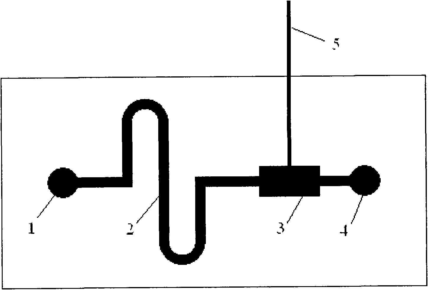
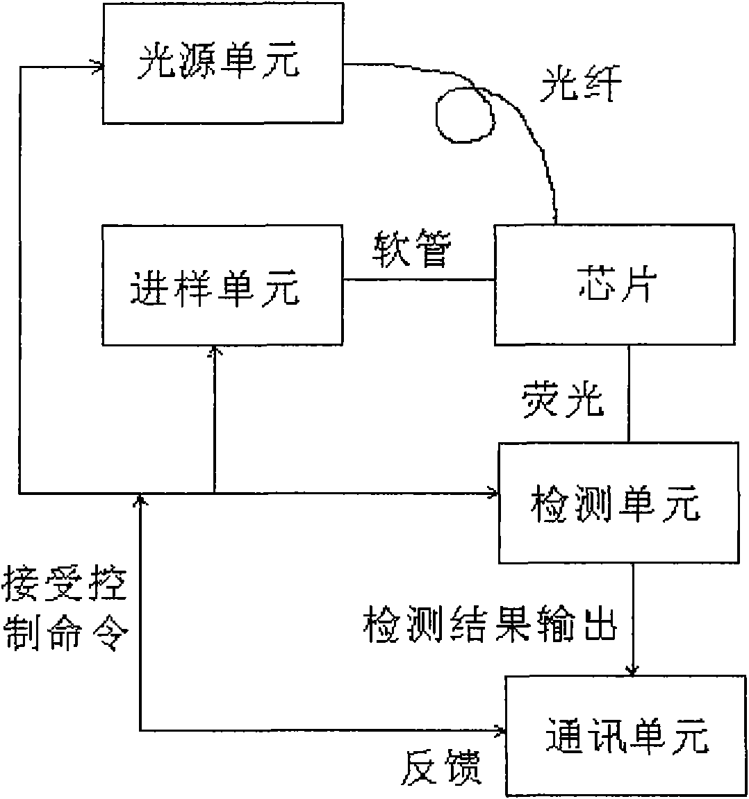
[0054] (1) Directly use the control panel on the microfluidic chip system to issue control commands: turn on the power supply, LED light source and photomultiplier tube in turn, and the LED excitation light is transmitted to the detection area of ​​the microfluidic chip through optical fibers;

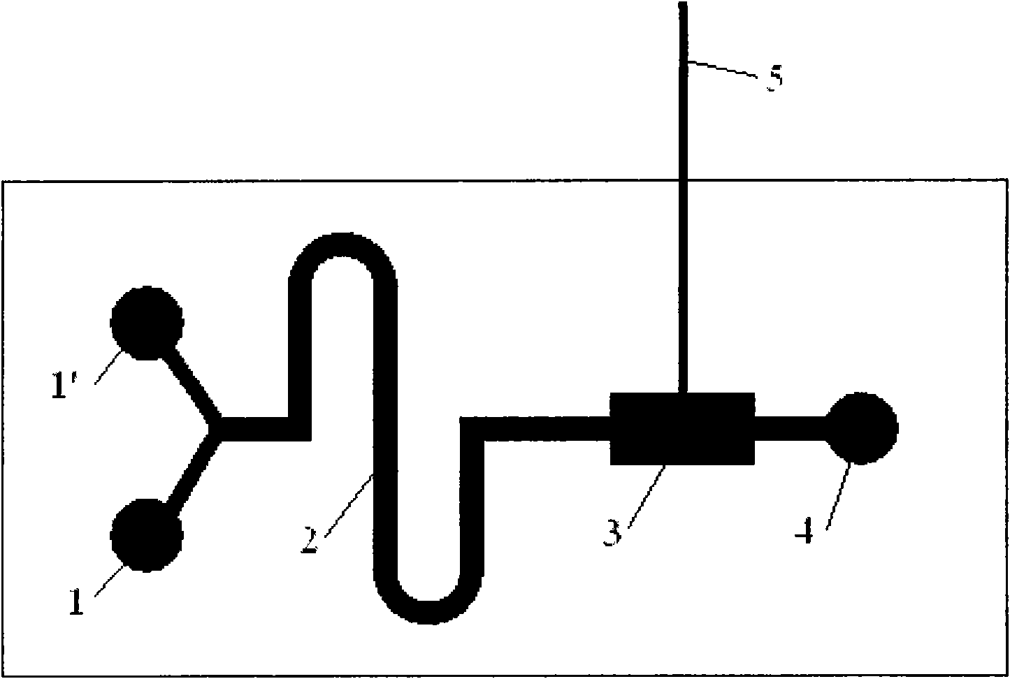
[0055] (2) Directly use the control panel on the microfluidic chip system to issue a pump start command, and the fluorescent substance (FITC standard solution) is introduced into the chip from the injection port under the drive of the pump;

[0056] (3) When flowing through the detection area, directly use the control panel on the microfluidic chip system to issue a pump shutdown command, the pump stops, and the detection unit detects the fluorescent light intensity (relative light intensity), and detects for 1 minute;

[0057] (4) The communication unit receives the detection result sent by the detection unit, and directly displays it on the display screen on the microfluidic chip syst...

test approach 2

[0062] (1) The computer control program is used to issue control commands: turn on the power supply, LED light source and photomultiplier tube in turn, and the LED excitation light is transmitted to the detection area of ​​the microfluidic chip through the optical fiber;

[0063] (2) The computer control program is used to issue a pump start command, and the fluorescent substance (FITC standard solution) is introduced into the microfluidic chip from the injection port under the drive of the pump;

[0064] (3) When flowing through the detection area, the program control issues a command to shut down the pump, the pump stops, and the detection unit detects the fluorescent light intensity (relative light intensity), and detects for 1 minute;

[0065] (4) The communication unit receives the detection result sent by the detection unit and transmits it to the computer;

[0066] (5) The program control issues a pump-on command, and after the solution flows out of the chip, the progra...


PUM

PropertyMeasurementUnit
volumeaaaaaaaaaa

Abstract

The invention discloses an integrated micro-fluidic chip system, which comprises a micro-fluidic chip, a light source unit, a sample introduction unit, a detection unit and a communication unit, wherein the micro-fluidic chip is connected with the light source unit through optical fibers and connected with the sample introduction unit through a hose; and the communication unit is electrically connected with the detection unit, the light source unit and the sample introduction unit. When used for detecting biochemical substances having a fluorescence response property in a fluid sample, the system can solve the problems in prior art such as time consumption, large reagent and sample consumption, complex operation and the like, can realize fluorescence detection under various conditions, hasthe advantages of high integration, quick analysis, high flexibility, little sample consumption, simple operation, quantitative analysis, online real-time detection and the like, has a compiling control degree that allows for combined use with a computer, independent operation, and can be used as a sensor unit in a wireless sensor network.

Description

technical field [0001] The invention relates to the technical field of microfluidic chips and testers, in particular to an integrated microfluidic chip system, including a microfluidic chip and the system. Background technique [0002] Microfluidic chip is a new type of biochemical chip developed in the 1990s on the basis of multi-disciplinary interdisciplinary and multi-technical integration of microelectromechanical system (MEMS) technology, life science, analytical science and information science. analytical skills. [0003] A microfluidic chip refers to the processing and control of channels with tens to hundreds of microns10 -9 ~10 -8 Scientific and technical system for liquids in liter volume. Micro-electro-mechanical systems (MEMS) technology is usually used to fabricate micro-channel networks on silicon wafers, glass or other material substrates, build micro-biochemical analysis units and systems, and integrate multiple units or modules with different functions th...

Claims


Application Information

Patent Timeline
Patent Type & Authority Applications(China)
IPC IPC(8): G01N33/50G01N21/64
Inventor 崔大付陈兴刘长春张璐璐李亚亭
Owner INST OF ELECTRONICS CHINESE ACAD OF SCI
Why Eureka
Try Eureka