
One-step forming process for sintered NdFeB permanent magnet of motor and mould thereof

A molding process, neodymium-iron-boron technology, applied in the manufacture of inductors/transformers/magnets, circuits, electrical components, etc., can solve problems such as time-consuming, labor-intensive and expensive, unstable oil pressure, and large pressure changes on the upper cylinder

Inactive Publication Date: 2009-11-18
宁波永久磁业有限公司
View PDF0 Cites 5 Cited by
  • Summary
  • Abstract
  • Description
  • Claims
  • Application Information

AI Technical Summary

Problems solved by technology

Since this process does not have a micro-pressure protection device for demoulding, it mainly relies on the pressure of the upper cylinder of the press to complete the pressure maintaining action. Due to the high pressure of the press, which can reach 63 tons, it will be affected by factors such as oil volume and temperature, which will cause insufficient oil pressure. Stable, the pressure of the upper cylinder changes greatly, resulting in a low pass rate of product cracking
The magnet mold for magnetic field orientation pressing is square, so when the pressed magnet is applied to the motor, the square magnet must be machined into a tile-shaped magnet, which not only increases the difficulty of the manufacturing process, but also takes time and labor. money, so improving the structure of the mold has become a very necessary topic

Method used


Image

  • One-step forming process for sintered NdFeB permanent magnet of motor and mould thereof
  • One-step forming process for sintered NdFeB permanent magnet of motor and mould thereof
  • One-step forming process for sintered NdFeB permanent magnet of motor and mould thereof

Examples


Embodiment Construction

[0020] The invention is described in further detail below in conjunction with the accompanying drawings;

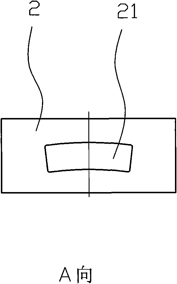
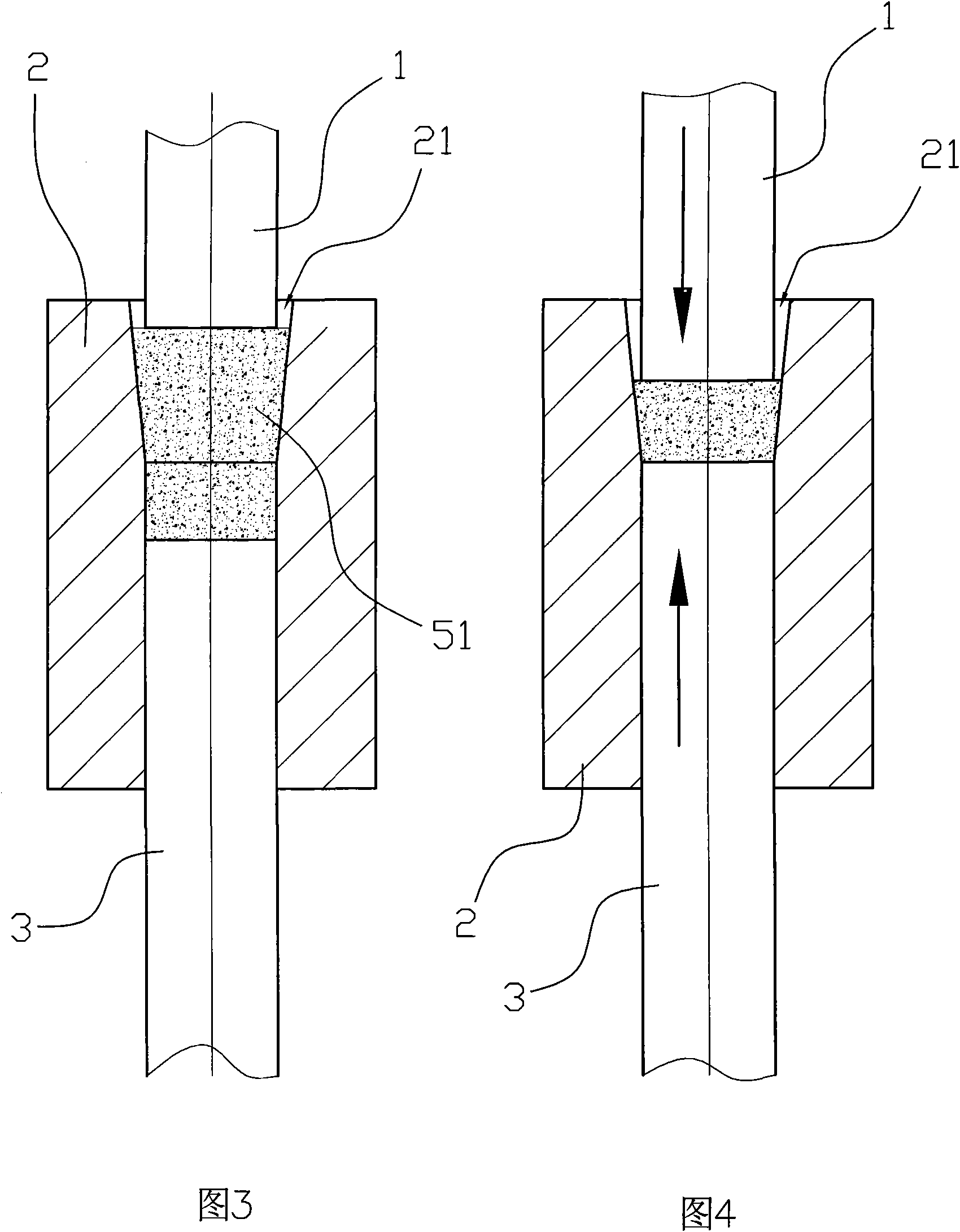
[0021] like Figure 1 to Figure 5 As shown, the one-time molding process of the sintered NdFeB permanent magnet used for motors in this embodiment includes the following steps: raw material preparation, smelting, ingot casting, crushing and powder making, magnetic field orientation pressing into magnets, and the magnetic field orientation pressing The formed magnet is a tile-shaped magnet 5, and the process of forming the tile-shaped magnet 5 by pressing is:

[0022] a. Place the required powder 51 in the tile-shaped cavity 21 in the female mold body 2;

[0023] b. Extend the upper pressing head 1 downwards into the tile-shaped cavity 21 of the female mold body 2 through a hydraulic press, and stop downward until the upper pressing head 1 contacts the powder material 51 in the tile-shaped cavity 21 of the female mold body 2 move;

[0024] c, then the magnet powder 51 i...


PUM


Abstract

The invention discloses a one-step forming process for a sintered NdFeB permanent magnet of a motor and a mould thereof. The one-step forming process comprises the following steps of preparing raw materials, smelting, casting, pulverizing, performing magnetic orientation press molding to the raw materials into a tile magnet, sintering, performing backfire and performing surface processing to the material into a finished product. The mould comprises an upper pressing head, a lower pressing head and a cavity die body, wherein the lower pressing head is connected with a hydraulic arm, a cavity of the cavity die body is a tile cavity, the upper pressing head is connected with a demolding micro-pressure protecting device, and the demolding micro-pressure protecting device is linked with a hydraulic machine. The invention has the advantages of saving the procedures of processing a square magnet into the tile magnet to achieve the aims of time-saving, money-saving and labor-saving; and changing the prior process of making the tilt material by using the square material to achieve the efficacy of processing corner-free materials and reducing the loss of powder quantity. The mould improves the designs and the process manufacture of a cavity die inner cavity and the upper and lower pressing heads. A forming bidirectional pressing special device and the demolding micro-pressure protecting special device are adopted to ensure the even density of a forming blank and reduce the phenomena of hidden cracking, edge breaking, corner defect, and the like caused by the density difference.

Description

technical field [0001] The invention relates to a one-time molding process and mold for a sintered NdFeB permanent magnet used in a motor. Background technique [0002] NdFeB permanent magnet materials have been widely used in many fields such as electronics, computers, automobiles, machinery, energy, and medical equipment due to their high magnetic energy, high coercive force, and high operating temperature. The sintered NdFeB permanent magnet tiles used for motors occupy an important position. The manufacturing process of the existing sintered NdFeB series permanent magnet materials is as follows: raw material preparation → smeltingingot casting → crushing powdermagnetic field orientation pressing into a square Magnetsinteringtemperingmachining into a tile-shaped magnet→surface treatment→testing. Since this process does not have a micro-pressure protection device for demoulding, it mainly relies on the pressure of the upper cylinder of the press to complete the p...

Claims


Application Information

Patent Timeline
IPC IPC(8): H02K15/03H01F41/02B22F3/16
Inventor 任荷芬周鸿波宋小明何国平张应海任春德陈振龙
Owner 宁波永久磁业有限公司
Learn More