Fiberguide grating sensor and manufacturing method thereof

A technology of grating sensor and optical fiber waveguide, which is used in optical waveguide light guide, transmission of sensing components using optical devices, fluid pressure measurement using optical methods, etc. To achieve the effect of high sensitivity, strong high temperature resistance, good measurement accuracy and multiplexing ability

Inactive Publication Date: 2011-05-25
UNIV OF ELECTRONICS SCI & TECH OF CHINA
View PDF1 Cites 0 Cited by
  • Summary
  • Abstract
  • Description
  • Claims
  • Application Information

AI Technical Summary

Problems solved by technology

[0003] In fiber optic sensors, the sensors used for temperature, strain and pressure measurement are mainly fiber Bragg gratings (FBG) and Fabry interferometers. The application has been greatly restricted, but its small cross-sensitivity is very suitable for temperature, strain and pressure measurement. However, the current optical fiber sensor uses a catheter to connect two sections of optical fiber, which has poor mechanical stability and is not durable. High temperature, its production mainly relies on manual production and packaging, and its yield and product repetition rate cannot be guaranteed
[0004] JP2001280922 and WO2005121697 disclose a F-P sensor. Due to the corrosion process, it is only suitable for multi-mode optical fibers. The sensor cavity must be a multi-mode optical fiber, and the production efficiency is low. It is difficult to make a pressure sensor by cutting the optical fiber; one optical reflective surface of the FAP sensor is a corroded curved concave surface, and its reflection performance is not good, resulting in poor optical performance of the FAP sensor and low contrast of the sensor reflection stripes (<10dB), so that the measurement accuracy is limited; one end of the sensor is a multi-mode fiber, the sensor has a large insertion loss, poor optical performance, and the connection loss with the existing ordinary single-mode fiber is large
The interference fringes of the Fappa cavity are wide, the multiplexing ability is not strong, and the signal demodulation is complicated

Method used


Image

  • Fiberguide grating sensor and manufacturing method thereof
  • Fiberguide grating sensor and manufacturing method thereof
  • Fiberguide grating sensor and manufacturing method thereof

Examples


Embodiment 1

[0015] A method for manufacturing an optical fiber waveguide grating sensor, comprising the following steps:

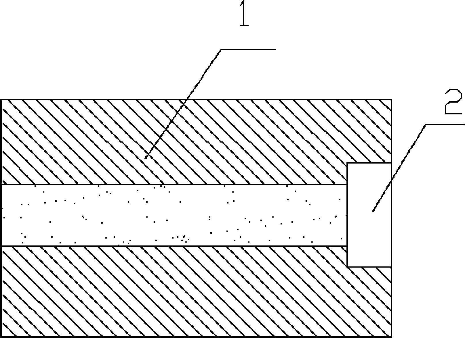
[0016] Step 1. Laser machining a groove 2 on the end face of the optical fiber 1, such as figure 1 shown;

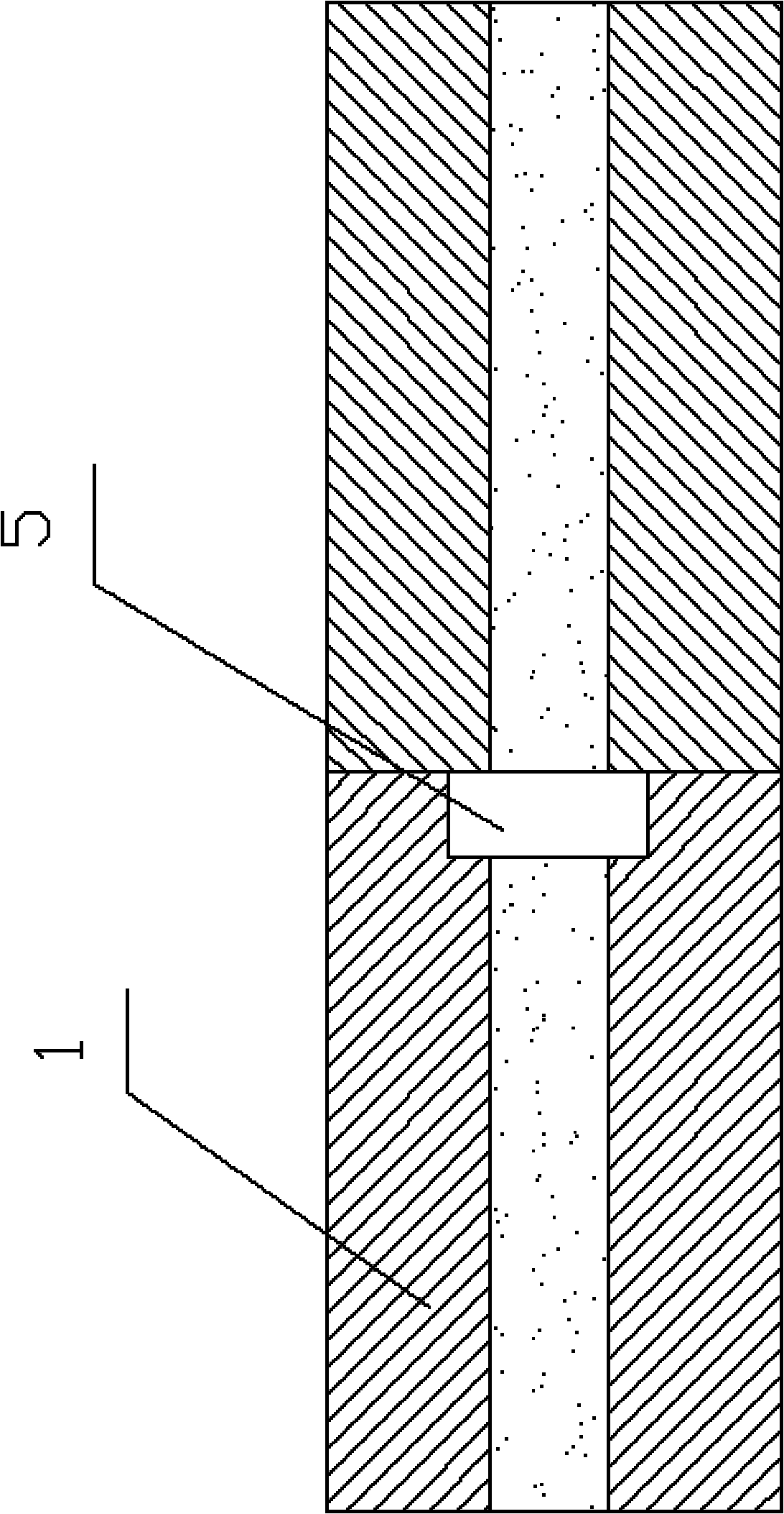
[0017] Step 2. Splice a section of connected optical fiber outside the groove 2 processed in step 1. The groove 2 forms a cavity 5, such as figure 2 shown;

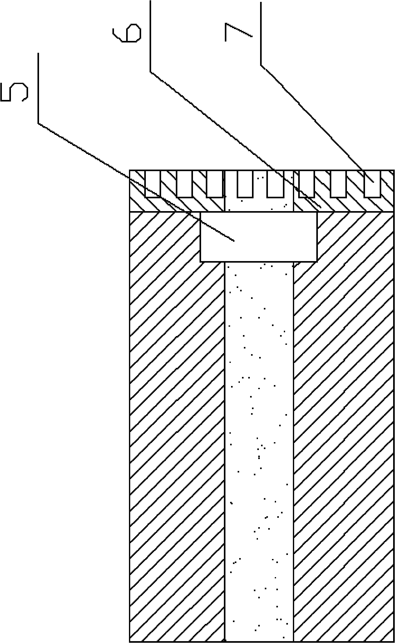
[0018] Step 3: Cut the connected optical fiber on the outer end face of the cavity 5 to form a waveguide diaphragm 6, and then process a plurality of periodic microgrooves 7 on the waveguide diaphragm 6 to form a periodic waveguide grating structure, and thus the present invention is produced. Fiber-optic waveguide grating sensors, such as image 3 As shown, the fiber optic sensor can be used to measure parameters such as temperature, refractive index and pressure.

Embodiment 2

[0020] On the basis of step 3 of embodiment 1, there is also step 4, welding the protective optical fiber 8 with a microgroove on the end face of the waveguide diaphragm 6 to protect the waveguide diaphragm 6, and the optical fiber waveguide of the present invention is produced Grating sensors such as Figure 4 shown. Compared with Example 1, this structure is more resistant to external interference, and there is no cross-sensitivity between refractive index and pressure.

Embodiment 3

[0022] A method for manufacturing an optical fiber waveguide grating sensor, comprising the following steps:

[0023] Step 1. Weld a section of hollow fiber on the end face of fiber 1, and then cut the hollow fiber to form groove 2 in the fiber core, such as Figure 5 shown;

[0024] Step 2 and step 3 are the same as in Embodiment 1, and the fiber waveguide grating sensor of the present invention is produced.


PUM


Abstract

The present invention provides a fiberguide grating sensor, having advantages of easier demodulation, high measurement precision and stronger multiplexing capability. The fiberguide grating sensor includes an optical fiber and an optical fiber to be joined, the end face of the optical fiber is provided with a groove, the optical fiber is connected with the optical fiber to be joined through buttjunction, the groove is formed to a cavity, the optical fiber to be joined is formed to a waveguide diaphragm, and the waveguide diaphragm is processed with a plurality of periodicity microflutes. By preparing a periodic waveguide grating structure on the waveguide diaphragm, it is capable of forming a waveguide grating for reflecting a specific wavelength, the bandwidth of the reflected wavelengthis narrow, and it is capable of obtaining the better measurement precision and the multiplexing capability; comparing with the common optical fiber grating, the waveguide grating with a cavity structure has a high sensitivity, and is capable of sensing the outside temperature, pressure and refractive index variation directly; by employing a whole optical fiber structure, the invention has a stronghigh temperature resistance capability, and it is capable of changing the range of the sensor by changing the dimension of the optical fiber and the diameter of the cavity.

Description

technical field [0001] The invention belongs to the technical field of optical fiber sensing, and in particular relates to an optical fiber waveguide grating sensor which can be used to measure temperature, refractive index and pressure and a manufacturing method thereof. technical background [0002] In the large family of sensors, fiber optic sensors have a series of advantages such as intrinsically safe, free from electromagnetic interference, convenient for networking and long-distance telemetry, and suitable for harsh environments, and have gradually become one of the mainstream development directions of the new generation of sensor technology. [0003] In fiber optic sensors, the sensors used for temperature, strain and pressure measurement are mainly fiber Bragg gratings (FBG) and Fabry interferometers. The application has been greatly restricted, but its small cross-sensitivity is very suitable for temperature, strain and pressure measurement. However, the current op...

Claims


Application Information

Patent Timeline
Patent Type & Authority Patents(China)
IPC IPC(8): G01D5/26G01K11/32G01L1/24G01L11/02G01N21/41G02B6/02G01K11/3206
Inventor 冉曾令饶云江
Owner UNIV OF ELECTRONICS SCI & TECH OF CHINA
Why Eureka
Try Eureka