Scintillation crystal array detecting device

A technology of scintillation crystal array and detection device, which is applied in measurement device, radiation measurement, X/γ/cosmic radiation measurement and other directions, can solve the problems of reducing photon collection efficiency, increasing the degree of noise influence, and failing to realize equal proportion distribution of light. , to achieve the effect of high transmission effect, balanced signal-to-noise ratio, and reduced volume and weight

Inactive Publication Date: 2010-02-10
PEKING UNIV
View PDF1 Cites 38 Cited by
  • Summary
  • Abstract
  • Description
  • Claims
  • Application Information

AI Technical Summary

Problems solved by technology

However, since the optical fiber is only connected by opening a small hole on the upper and lower surfaces of the crystal, only a part of the photons can enter the fiber through the small hole, which reduces the photon collection efficiency of the system.
In addition, the number of photons collected by the two optical fibers connected to the upper and lower surfaces of the crystal depends on the depth of interaction between the γ photons and the crystal, and the equal distribution of light cannot be achieved.
It may happen that one fiber collects a large number of photons while the other fiber collects a smaller number of photons, which increases the influence of noise on the photon collection results

Method used


Image

  • Scintillation crystal array detecting device
  • Scintillation crystal array detecting device
  • Scintillation crystal array detecting device

Examples


Embodiment 1

[0040] The crystal array in this embodiment is exposed to the gamma-ray environment generated by the nuclide drug injected into the subject, and the crystals in the crystal array generate fluorescent photons after receiving the gamma photons.

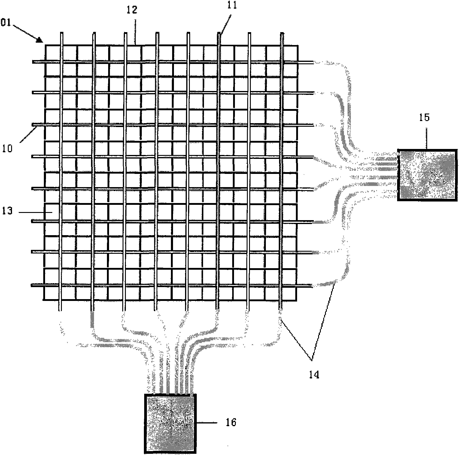
[0041] In this embodiment, a set of optical fiber system based on optical calculation is used to connect with the crystal array 01, such as figure 1 Shown is the plane structure diagram of the scintillation crystal array detection device, the optical fibers are distributed into M rows and N columns, so that each row of independent scintillation crystals 13 is connected to a row of optical fibers 10, and each column of independent scintillation crystals 13 is connected to a column Fiber 11. All row optical fibers 10 are all connected with the first position sensitive photomultiplier tube 15, all row optical fibers 11 are all connected with the second position sensitive photomultiplier tube 16, utilize the first position sensitive photomu...

Embodiment 2

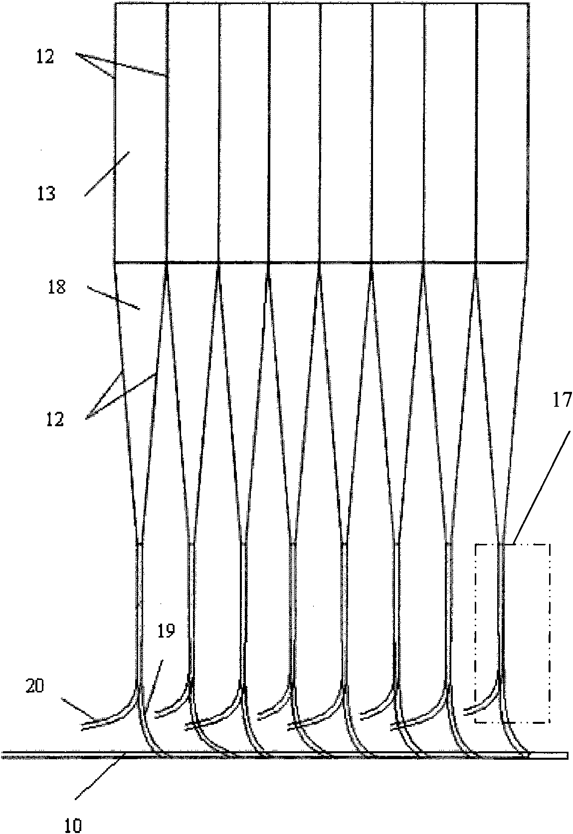
[0051] As another embodiment of the present invention, the structure of the crystal array detection device in this embodiment is the same as that of Embodiment 1, and the NaI (Tl) scintillation crystal of the array is used in the single photon emission tomography imaging system (SPECT) (each volume 4×4×10mm 3 ), the crystal array 01 is exposed to the 140keV γ-ray environment generated by the nuclide drug injected into the subject. The NaI(Tl) crystal absorbs gamma photons 24 with an energy of 140 keV, and each keV of energy can generate about 40 fluorescent photons 26 with a wavelength range of 400 to 500 nm, and the spectral peak is at about 415 nm. Therefore, about 5600 fluorescent photons can be generated after each γ photon is absorbed by NaI(Tl)26. The decay time of the NaI crystal is 0.25 μs, and within 1 μs (about 4 times of the decay time of the NaI crystal) after the 140 keV gamma photon is absorbed, all the fluorescent photons 26 are radiated.

[0052] Figure 4 A...


PUM


Abstract

The invention relates to a scintillation crystal array detecting device, which comprises a crystal array, M*N light guides, an optical fiber splitter unit, an optical fiber merging unit and an opticalfiber signal reading unit, wherein the crystal array comprises M*N crystals for generating fluorescence photons, M represents the number of rows, and N represents the number of columns; each light guide is connected with the surface of a crystal to collect and transmit the fluorescence photons generated by the crystal; the optical fiber splitter unit is used for splitting fluorescence photons transmitted by each light guide into two paths of optical fibers which are a row transmission optical fiber and a column transmission optical fiber to transmit the fluorescence photons; the optical fibermerging unit is used for fusing row transmission optical fibers corresponding to light guides connected with the same row of crystals into a row optical fiber and fusing column transmission optical fibers corresponding to light guides connected with the same column of crystals into a column optical fiber; and the optical fiber signal reading unit is connected with the row optical fibers and the column optical fibers to recognize the numbers of the rows in which the row optical fibers transmitting the fluorescence photons are and the numbers of the columns in which the column optical fibers transmitting the fluorescence photons are to further determine the position of scintillation crystals and detect the total quantity and energy of received fluorescence photons. The device is reduced incost, volume and weight and has high position resolution and fluorescence collection efficiency.

Description

technical field [0001] The invention relates to a gamma ray imaging system, in particular to a scintillation crystal array detection device for measuring the distribution of radioactivity in an object in the imaging system. Background technique [0002] Gamma-ray imaging systems are widely used in the field of non-invasive inspection of the internal conditions of objects, especially some medical imaging systems, such as Positron Emission Computed Tomography (PET) systems and Single Photon Emission Computed Tomography (Single Photon Emission Computed Tomography) , SPECT) system. These systems often use flat-panel scintillation crystals or arrays of scintillation crystals as detectors to measure the distribution of radioactivity within the object. Taking the sodium iodide (NaI) scintillation crystal array as an example, whenever the NaI scintillation crystal absorbs γ-rays, it will emit fluorescent photons whose number is proportional to the energy of the γ-rays. In this arr...

Claims


Application Information

Patent Timeline
Patent Type & Authority Applications(China)
IPC IPC(8): G01T1/202
Inventor 曹文田凌松云
Owner PEKING UNIV
Why Eureka
Try Eureka