
Device and method for reducing emission of tail gas

A tail gas and compression device technology, which is applied in exhaust devices, noise reduction devices, separation methods, etc., can solve the problems of short absorber replacement cycle, lower absorption efficiency, corrosion, etc., achieve good environmental protection and economic benefits, and reduce emissions , a wide range of effects

Inactive Publication Date: 2010-02-17
ENN SCI & TECH DEV
View PDF0 Cites 13 Cited by
  • Summary
  • Abstract
  • Description
  • Claims
  • Application Information

AI Technical Summary

Problems solved by technology

This kind of scheme can be carried out under normal temperature without any additional any catalytic treatment, but has the following disadvantages: 1) Na 2 o 2 easy with h 2 O and CO in the air 2 The reaction occurs, which unnecessarily consumes part of the Na in the absorber to a certain extent 2 o 2 dose, lowers the CO 2 The absorption efficiency, and Na 2 o 2 with H 2 The NaOH produced by the O reaction is corrosive; 2) The exhaust gas temperature of the gasoline engine is as high as 700°C to 1000°C, while the NaOH 2 o 2 The melting point of is about 675°C, and it hardly decomposes when it is in a molten state, so for a gasoline engine, the exhaust temperature is too high for a reason for the partial failure of the absorber (ie, thermal deactivation); 3) due to Na 2 o 2 The reagent is loaded into the absorber at one time, and as the main body of the reaction, it is always being consumed, and a certain amount of by-product Na is produced at the same time. 2 CO 3 trapped in the absorber, so CO 2 Absorber replacement intervals may be shorter

Method used


Image

  • Device and method for reducing emission of tail gas
  • Device and method for reducing emission of tail gas
  • Device and method for reducing emission of tail gas

Examples


Embodiment Construction

[0046] A tail gas emission reduction device and a tail gas emission reduction method provided by the present invention will be described in detail below with reference to the accompanying drawings.

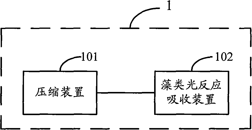
[0047] Embodiments of the present invention provide a tail gas emission reduction device, such as figure 1 As shown, the tail gas emission reduction device 1 is connected to the output end of the three-way catalytic converter commonly used for emission reduction of existing motor vehicles.

[0048] Such as figure 1 As shown, the exhaust emission reduction device provided by the embodiment of the present invention includes: a compression device 101 and an algae light reaction absorption device 102 . in:

[0049]One end of the compression device 101 is connected with the three-way catalytic converter in the motor vehicle, and the other end is connected with the algae light reaction absorption device 102 . The function of the compression device is to receive and compress the tail ...


PUM


Abstract

The invention discloses a device and a method for reducing the emission of tail gas. The provided device for reducing the emission of tail gas comprises a compression device and an alga photoreactionabsorption device, wherein one end of the compression device is connected with a three-way catalytic converter, and the other end is connected with the alga photoreaction absorption device and used for receiving and compressing tail gas generated by the catalytic reaction by the three-way catalytic converter and uniformly leading the compressed tail gas into the alga photoreaction absorption device; and the alga photoreaction absorption device is used for absorbing carbon dioxide in the tail gas output by the compression device by utilizing the photosynthetic reaction of microalgae. The device for reducing the emission of tail gas is green and environment-friendly, and does not generate corrosive chemical substances during reaction, and is applied to all locomotives with emission of carbon dioxide, and has wide application range. The invention effectively reduces the emission of carbon dioxide under the condition of global gradually warming, and has favorable environment-friendly benefits and economic benefits.

Description

technical field [0001] The invention relates to the field of biological environmental protection engineering, in particular to a tail gas emission reduction device and a tail gas emission reduction method. Background technique [0002] The main pollutants of vehicle exhaust include carbon monoxide, hydrocarbons, nitrogen oxides and carbon dioxide. Existing control vehicle exhaust mainly contains the following several ways: [0003] 1) Improve fuel quality, increase fuel octane number to increase anti-knock ability, etc. [0004] 2) Improve the combustion process and adopt internal purification technology to prevent harmful emissions. [0005] 3) Off-machine post-processing technology, such as three-way catalytic technology, non-equilibrium plasma treatment technology, nanotechnology and other high-tech technologies. [0006] 4) Improve engine technology. [0007] 5) Use clean energy, such as electric energy, liquefied petroleum gas, compressed natural gas, hydrogen and a...

Claims


Application Information

Patent Timeline
IPC IPC(8): F01N3/08B01D53/84F01N3/10F01N3/24B01D53/92
CPCY02T10/12
Inventor 吴洪李青陈红涛
Owner ENN SCI & TECH DEV
Features
  • Generate Ideas
  • Intellectual Property
  • Life Sciences
  • Materials
  • Tech Scout
  • Unparalleled Data Quality
  • Higher Quality Content
  • 60% Fewer Hallucinations
Learn More