Method for synchronously performing parallel detection of various biomarkers and chip test paper
A technology of biomarkers and markers, applied in biological testing, material inspection products, fluorescence/phosphorescence, etc., can solve the problems of long detection time, rapid detection cannot be quantified, etc., and achieve the effect of easy portability and easy use
- Summary
- Abstract
- Description
- Claims
- Application Information
AI Technical Summary
Problems solved by technology
Method used
Image
Examples
preparation example Construction
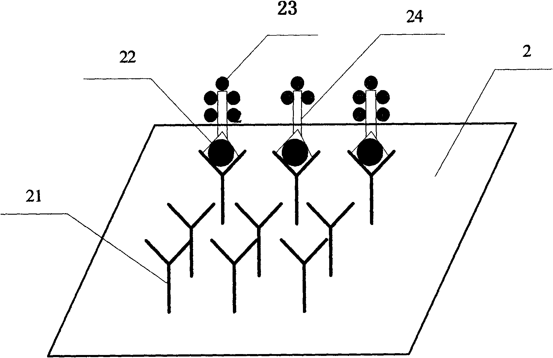
[0046] Preparation of the ligand Bn-labeled signal substance: the source and type of the ligand Bn are the same as the ligand An (n=1, 2, 3, 4...), and the labeled signal substance can be fluorescein fluorescein (fluorescein: FITC, Cy2 TM, Alexa TM 488, Cy3 TM, Alexa TM 546 conventional fluorescein), fluorescent protein (GFP, R-PE, R-PC), nano gold, silver, nano fluorescent microspheres, quantum dots, rare earth elements, radioactive elements, small molecule chemicals or pigments). The ligand Bn and the labeling signal substance can be connected together by corresponding physical, chemical or biological methods through their corresponding physical and chemical properties to make them exist stably.
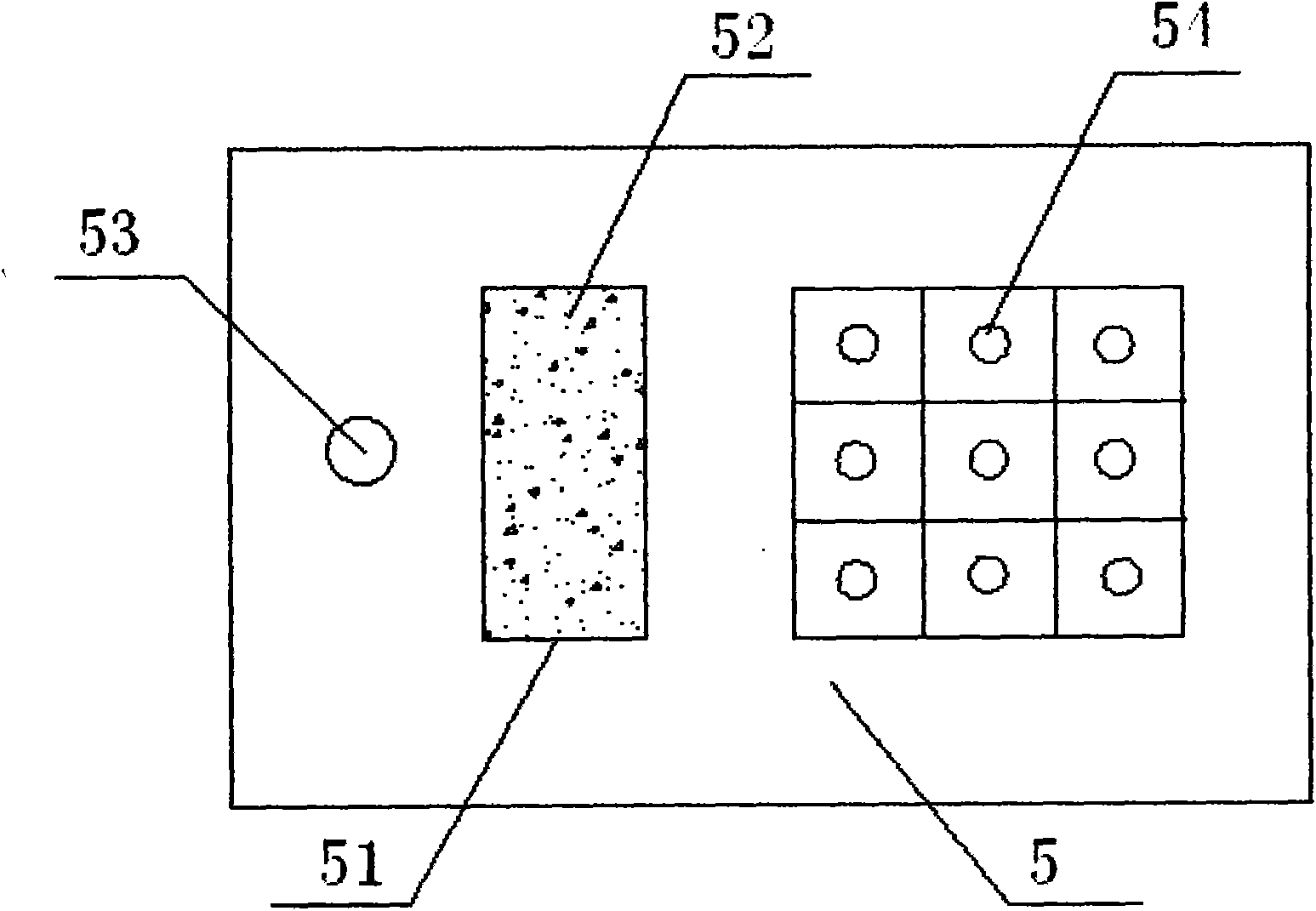
[0047] Production of chip test paper: chip test paper can have various shapes according to its fluidic method, and its basic components include: sample injection hole, storage position of ligand Bn marker, ligand An micro-arrangement and support, sample flow driving force Device (...
specific Embodiment
[0053] The implementation mode of the chip test paper detector:
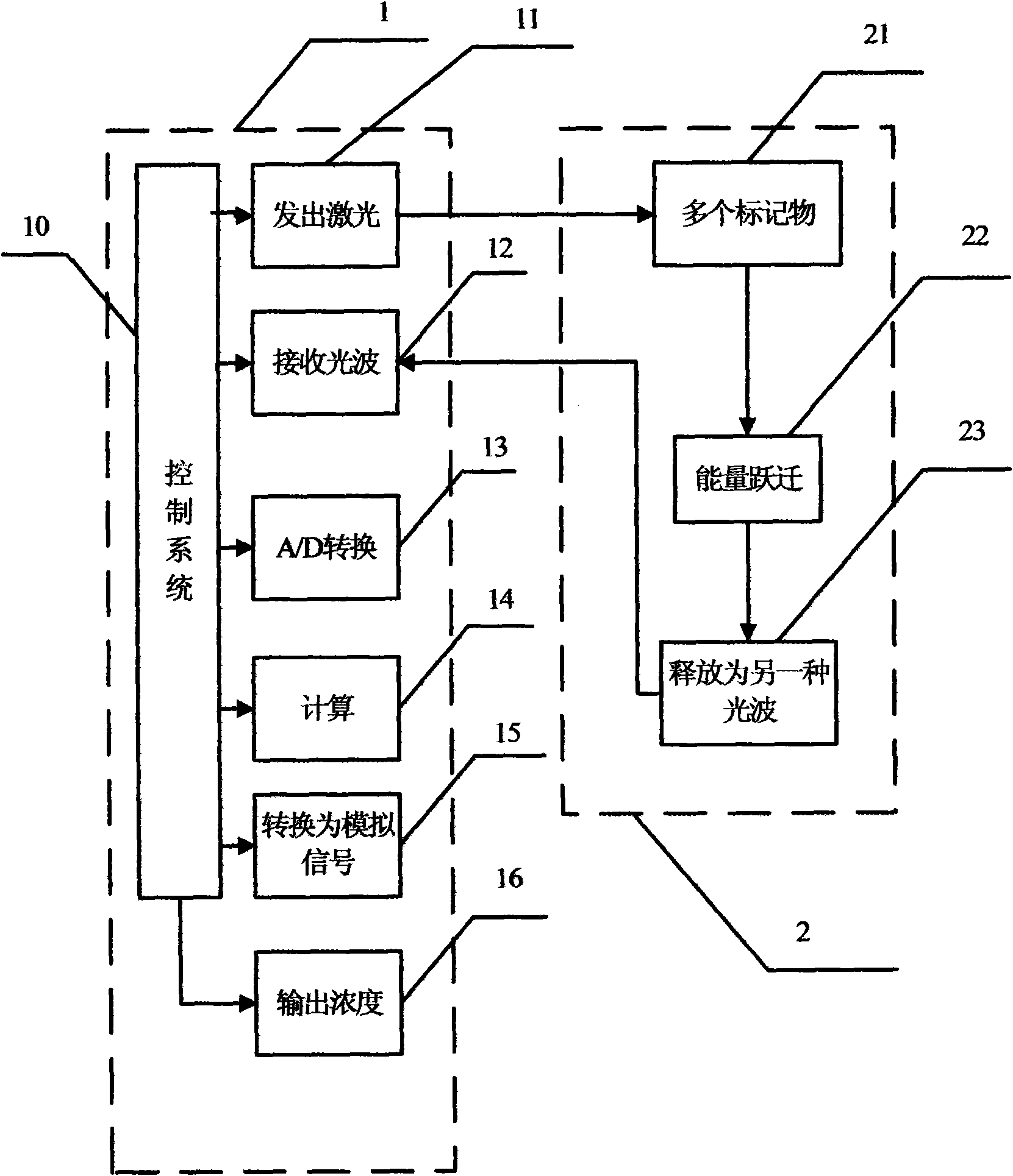
[0054] see Figure 4 As shown, the detector includes: laser 31, filter group 32, optical filter 33, dichroic mirror 38, mirror 35, first objective lens 34, second optical filter 36, second objective lens 37, diaphragm 40 And chip test paper 39, and PMT (photomultiplier tube) components, AMP (signal amplifier) components, converter A / D (signal data converter) components, CD chip, output printing equipment, main board and power supply equipment (not shown in the figure ).
[0055] Detector assembly and testing
[0056] According to the design diagram, connect the optical components in the instrument box in turn, and distribute the power supply and control board, and check the working conditions of each section of lines and components in turn to check whether they meet the requirements. After fully conforming, turn on the main board control program and power supply, and test the working condition of the system...
Embodiment approach
[0061] The material of the chip test paper can be NC film or glass sheet or plastic sheet, etc. The chip dot matrix is 5X6 or other arrangements (determined according to the specific product), the spacing is 1mm, the spot diameter is 10um-500um, and the overall width of the test paper is 3-30mm. Length range: 30-100mm. Appearance includes sampling hole, chip irradiation window, sealing card, positioning mark, etc. The internal structure of the chip test paper includes: filter paper, glass fiber where the ligand of the signal marker is located, and the ligand matrix (including test points, calibration points and quality control points), etc.
[0062] According to the above design and production test, the chip test paper detector fully meets its advantages of fast, sensitive, quantitative detection, multiple joint inspections, and easy to carry. It is a product with a wide range of applications in the future, which will play a role in promoting the development of clinical tes...
PUM
 Abstract
Description
Claims
Application Information
 - R&D
- Intellectual Property
- Life Sciences
- Materials
- Tech Scout
- Unparalleled Data Quality
- Higher Quality Content
- 60% Fewer Hallucinations
Browse by: Latest US Patents, China's latest patents, Technical Efficacy Thesaurus, Application Domain, Technology Topic, Popular Technical Reports.
© 2025 PatSnap. All rights reserved.Legal|Privacy policy|Modern Slavery Act Transparency Statement|Sitemap|About US| Contact US: help@patsnap.com


