Piezoelectric transformer

A technology of piezoelectric transformers and piezoelectric substrates, applied in the field of piezoelectric transformers, can solve the problems of copper loss leakage flux increase, electromagnetic noise, hysteresis loss, etc.

Inactive Publication Date: 2012-07-04
KYOCERA CORP
View PDF2 Cites 0 Cited by
  • Summary
  • Abstract
  • Description
  • Claims
  • Application Information

AI Technical Summary

Problems solved by technology

[0002] In the existing switching power supply, although an electromagnetic transformer based on electromagnetic induction can be used as a transformer, the electromagnetic transformer at high frequency has hysteresis loss, eddy current loss and skin effect. The problem of increasing losses
In addition, the miniaturization and thinning of the electromagnetic transformer itself leads to copper loss due to the multi-turn ultra-thin wire wound, a decrease in magnetic coupling, and an increase in leakage flux. The reason for the efficiency of the circuit
In addition, there are problems such as electromagnetic noise due to winding

Method used


Image

  • Piezoelectric transformer
  • Piezoelectric transformer
  • Piezoelectric transformer

Examples


Embodiment 1

[0071] Computer simulations using the finite element method were performed for the piezoelectric transformer of the present invention.

[0072] Pb(Ti, Zr)O is assumed as the material of the piezoelectric transformer3 Piezoelectric material, in the simulation, set the piezoelectric constant d 31 =-125pC / m, relative permittivity εr=1420, Qm=1000, and calculated.

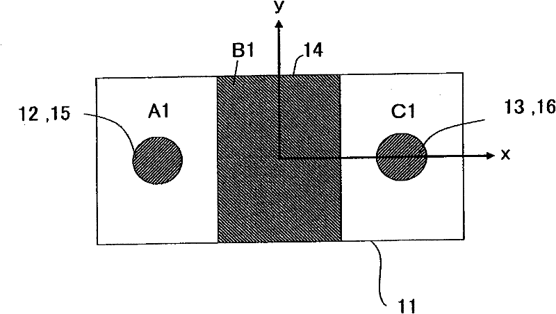
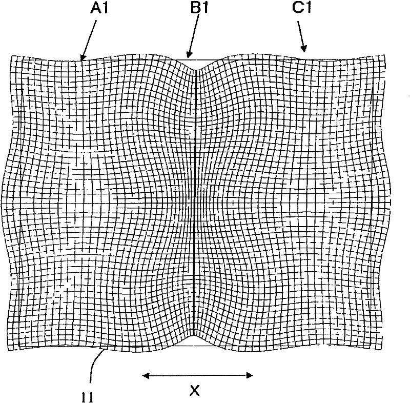
[0073] exist Figure 8 A mesh segmentation diagram of the finite element model used in the simulation is shown in . In the simulation, consider the symmetry of the piezoelectric transformer, as figure 2 As shown, the upper right part of the same figure is simulated using a 1 / 4 symmetric model. exist Figure 8 Among them, symbol 42 represents a 1 / 4 symmetry plane.

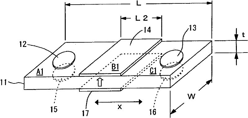
[0074] The dimensions of the piezoelectric transformer were assumed to be length L = 31.5 mm, width W = 26.0 mm, and thickness T of the piezoelectric substrate = 2.1 mm. In addition, the length Lin of the input part was set at 10.5 mm, the length Lout...

Embodiment 2

[0081] If the electrode area is reduced all the way to about 5% as in S1, regardless of the choice of deformation S XX A drop in efficiency can be confirmed in a large area. In particular, it can be seen that the peak of efficiency at frequencies lower than 170 kHz becomes smaller. Due to the impedance matching of the input circuit and the limitation of the driving IC, etc., in the case of actually having to use it in an electrode such as S1, although it is desirable to use it at a frequency near 175kHz, it is due to the spuriousness caused by the unwanted vibration mode near 170kHz. , so the usable frequency band is narrowed.

[0082] Therefore, as shown in FIG. 13 , a rectangular notch is formed in the peripheral portion of the piezoelectric transformer to try to control the parasitic. As shown in FIG. 13, if four notches are formed in the peripheral portion of the piezoelectric substrate, the spurious caused by unwanted vibration can be shifted to the low frequency side, ...

Embodiment 3

[0084] exist Figure 14 A circuit diagram of a piezoelectric transformer device in which two piezoelectric transformers are connected is shown as an example of a piezoelectric transformer device constituted by connecting a plurality of piezoelectric transformers. In the connection on the input side, the input parts of the two piezoelectric transformers are connected in series with respect to the input voltage. Assuming that the number of connected piezoelectric transformers is N, the electrostatic capacitance of the input part can be reduced to 1 / N of that of one piezoelectric transformer. On the other hand, in the connection on the output side, it is connected in parallel with respect to the load on the output side. In this way, although it is necessary to increase the input voltage by N times, the output power can also be increased by N times. It is also conceivable to overlap multiple piezoelectric transformers to form a block, but if a block is formed, the thickness of t...


PUM


Abstract

The invention provides a piezoelectric transformer which can reduce the capacity of an input unit and realize a impedance matching with a drive circuit of an input side. A piezoelectric transformer includes: a piezoelectric substrate (11) having both main surfaces of a rectangular shape; and input side electrodes (12, 13, 15, 16) and output side electrodes (14, 17) formed on the both main surfaces of the piezoelectric substrate (11). A pair of opposing input side electrodes (12, 13, 15, 16) are arranged on the both surfaces of the piezoelectric substrate (11) in the first input unit (A1) and the second input unit (A2). At least one of the pair of input side electrodes (12, 13, 15, 16) is a partial electrode arranged at the center portion of the main surface of the piezoelectric substrate (11) in the first input unit (A1) and the second input unit (A2).

Description

technical field [0001] The present invention relates to a piezoelectric transformer, and in particular to AC adapters and DC-DC converters used in various electronic devices, and cold cathode tube backlights for liquid crystal displays used in notebook computers, portable terminals, etc. A piezoelectric transformer in an inverter or the like of a source. Background technique [0002] In the existing switching power supply, although an electromagnetic transformer based on electromagnetic induction can be used as a transformer, the electromagnetic transformer at high frequency has hysteresis loss, eddy current loss and skin effect. There is a problem that the loss increases. In addition, the miniaturization and thinning of the electromagnetic transformer itself leads to copper loss due to the multi-turn ultra-thin wire wound, a decrease in magnetic coupling, and an increase in leakage flux. The reason for the efficiency of the circuit. In addition, there is a problem that e...

Claims


Application Information

Patent Timeline
Patent Type & Authority Patents(China)
IPC IPC(8): H01L41/107H01L41/187H02M3/24
CPCH01L41/047H01L41/107H10N30/87H10N30/40
Inventor 吉村健一西村道明
Owner KYOCERA CORP
Why Eureka
Try Eureka