Bimodule annular resonant cavity band-pass filter with direct feed planar structure

A ring resonator and ring resonator technology, applied in the microwave field, can solve the problems affecting the application of the filter, increase the insertion loss of the filter, etc., and achieve the effects of simple structure, small size, and easy production.

Inactive Publication Date: 2010-04-14
NANJING UNIV OF POSTS & TELECOMM
View PDF0 Cites 11 Cited by
  • Summary
  • Abstract
  • Description
  • Claims
  • Application Information

AI Technical Summary

Problems solved by technology

Most of the existing dual-mode filters use terminal capacitive coupling to feed the dual-mode resonant cavity. Due to the radiation and edge effects of the terminal capacitance, this feeding method will bring coupling loss, that is, feeding loss, which will increase The insertion loss of the filter affects the practical application of the filter

Method used


Image

  • Bimodule annular resonant cavity band-pass filter with direct feed planar structure
  • Bimodule annular resonant cavity band-pass filter with direct feed planar structure
  • Bimodule annular resonant cavity band-pass filter with direct feed planar structure

Examples


Embodiment 1

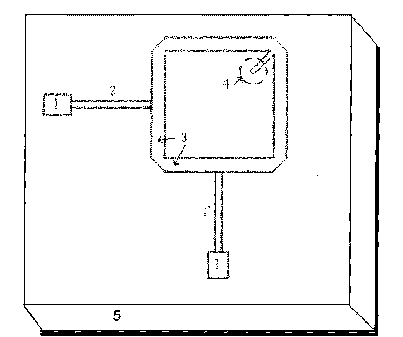
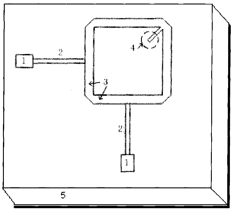
[0012] Embodiment 1 (compared with attached figure 1 ), the input / output microstrip line 1 takes a characteristic impedance of 50 ohms, the length of the ring resonator 3 is 12.0 millimeters, the line width is 1.0 millimeters, the length of the quarter-wavelength impedance converter 2 is 10.0 millimeters, and the end of the open-circuit microstrip line is loaded 4. The width is 0.7 mm, and the dielectric constant 10 is selected as the dielectric substrate 5. The thickness is 1.0 mm. In order to achieve good in-band matching of the band-pass filter, the length of the microstrip line loaded with an open end is 7.0 mm, and the width of the impedance transformer is 0.3 mm.

Embodiment 2

[0013] Embodiment 2 (compared with attached figure 1 ), the characteristic impedance of the input / output microstrip line 1 is 50 ohms, the length of the ring resonator 3 is 12.0 mm, the line width is 1.0 mm, the length of the impedance converter 2 is 10.0 mm, and the end open microstrip line loading 4 is 0.7 mm in width , The dielectric substrate 5 is selected to have a dielectric constant of 10 and a thickness of 1.0 mm. In order to achieve good in-band matching of the bandpass filter, the length of the microstrip line loaded with open end is 5.5 mm, and the width of the impedance transformer is 0.2 mm.

Embodiment 3

[0014] Embodiment 3 (compared with attached figure 1 ), the input / output microstrip line 1 takes a characteristic impedance of 50 ohms, the length of the ring resonator 3 is 12.0 millimeters, the line width is 1.0 millimeters, the length of the quarter-wavelength impedance converter 2 is 10.0 millimeters, and the end of the open-circuit microstrip line is loaded 4. The width is 0.7 mm, and the dielectric constant 10 is selected as the dielectric substrate 5. The thickness is 1.0 mm. In order to achieve good in-band matching of the bandpass filter, the length of the microstrip line with open end is 4.0 mm, and the width of the impedance transformer 2 is 0.1 mm.

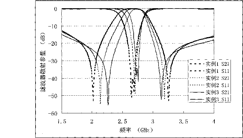
[0015] Control attached figure 2 , which gives the filter scattering parameter curves of Examples 1-3. It can be seen from the figure that the novel dual-mode filter design method can significantly improve the filter performance. It can be seen from the figure that the filter bandwidth can be adjusted by adopting d...


PUM


Abstract

The invention relates to a bimodule-plane band-pass filter with a novel structure, which can be widely applied in the design of a radio-frequency microwave passive circuit. The filter consists of a capacitive load formed by microstrip lines with open circuit at the tail end and an annular bimodule resonant cavity; the annular bimodule resonant cavity is square and consists of an annular resonator (3) and a microstrip line load (4) with open circuit at the tail end at the right-angle position of the annular resonator (3); two input/output microstrip lines (1) are adopted and are both impedance converters (2) with quarter wavelength; the two input/output microstrip lines (1) are directly connected with two adjacent edges on the annular resonator (3), and the two adjacent edges have opposite angles with the microstrip line load (4) with open circuit at the tail end; and the whole filter structure is made on a medium substrate (5) with metal coated on both surfaces, wherein one surface is etched to be a circuit, and the metal on the other surface is totally reserved to be used as a ground plate. On the premise of maintaining the advantages of the original bimodule filter, the bimodule-plane band-pass filter reduces the insertion loss of the filter and has adjustable bandwidth.

Description

technical field [0001] The invention relates to a miniaturized planar microwave band-pass filter manufactured by printed circuit board technology. The filter can be applied to microwave circuits and microwave integrated circuits in various electronic devices, and its use is beneficial to the integration and miniaturization of circuits, and belongs to the field of microwave technology. Background technique [0002] A filter is a passive device widely used in microwave and radio frequency applications, and its index directly affects the performance of the entire system. Common microwave filters are mostly made of metal waveguide / dielectric waveguide, coaxial line or planar microstrip line / stripline. In recent years, due to the increasingly strong demand for miniaturization and miniaturization of communication systems, as one of the key passive components in the system, the demand for miniaturization design of filters is also increasing. Compared with the realization of three...

Claims


Application Information

Patent Timeline
Patent Type & Authority Applications(China)
IPC IPC(8): H01P1/20H01P1/203H01P1/207
Inventor 陈董程崇虎
Owner NANJING UNIV OF POSTS & TELECOMM
Why Eureka
Try Eureka