

Method for purifying cyclic solvent in producing TDI
A technology of circulating solvent and purification tower, applied in chemical instruments and methods, organic chemistry, preparation of isocyanic acid derivatives, etc., can solve the problems of expensive, difficult to avoid, and burden on the slag removal system, and achieve remarkable results.
Inactive Publication Date: 2010-04-28
甘肃银光聚银化工有限公司 +1
View PDF0 Cites 26 Cited by
- Summary
- Abstract
- Description
- Claims
- Application Information
AI Technical Summary
Problems solved by technology
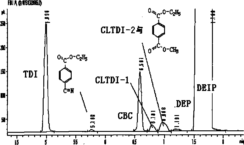
[0002] At present, the production of toluene diisocyanate (TDI) in the world generally adopts the following two processes: the first is to use diethyl isophthalate (DEIP) as a solvent, and carry out photochemical reaction under high pressure conditions, which is commonly called However, in the photochemical reaction of this process, the solvent diethyl isophthalate (DEIP) is easy to react with phosgene to generate m-ethyl benzoyl chloride (CBC), which is easy to cause Blockage of the reactor; in addition, due to the high price of diethyl isophthalate (DEIP), its large consumption will increase the cost of the final product toluene diisocyanate (TDI)
[0003] The second process uses o-dichlorobenzene (ODCB) as a solvent to carry out photochemical reaction under low pressure conditions, which is commonly called "light solvent production process"; the photochemical reaction of this process is carried out in a reactor with agitator In the process, it is difficult to avoid the reaction of toluene diamine (TDA) and toluene diisocyanate (TDI) in the reaction process, because the generation of this reaction reduces the yield of TDI products, and produces a large amount of residue to the slag removal system at the same time Bring burden; Another defect of this technique is, use a large amount of solvent o-dichlorobenzene (ODCB) to circulate in the system, increase the raw material of equipment and the consumption of power energy, have improved the production cost of TDI
[0020] and It is easy to cause the blockage of the photochemical reactor feed, and it reacts with phosgene to generate Most of the substance in the system is removed in the residue removal system in the form of residue, but a small part will adhere to high temperature areas, such as the tube wall of the heat exchanger, etc.
Method used
View moreImage
Smart ImageViewing Examples

Examples
Embodiment 1
[0055] Example 1: The continuous production process condition control is as follows:
[0056]
Embodiment 2
[0057] Example 2: The control of batch production process conditions is as follows:
[0058]
Embodiment 3
[0059] Example 3: The process conditions of batch production with ethanol as the remover are controlled as follows:
[0060] In this experiment, the raw material is also a solvent with low NCO concentration. The concentration measured by the chemical method is 2092PPM. The additional reactant is changed to ethanol. Because ethanol has a relatively low boiling point and is easier to volatilize, the ratio is increased, and the molar ratio of NCO: ethanol is 1:10, react.
[0061]
[0062]
Login to View More PUM
 Abstract
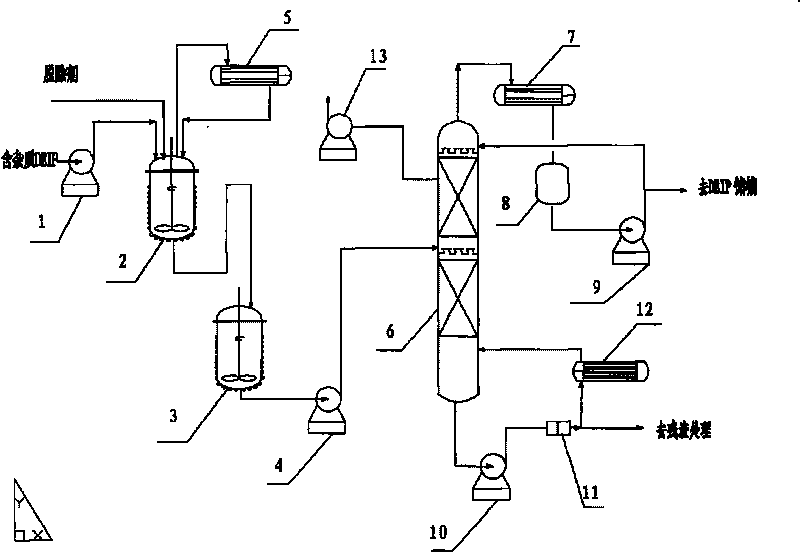
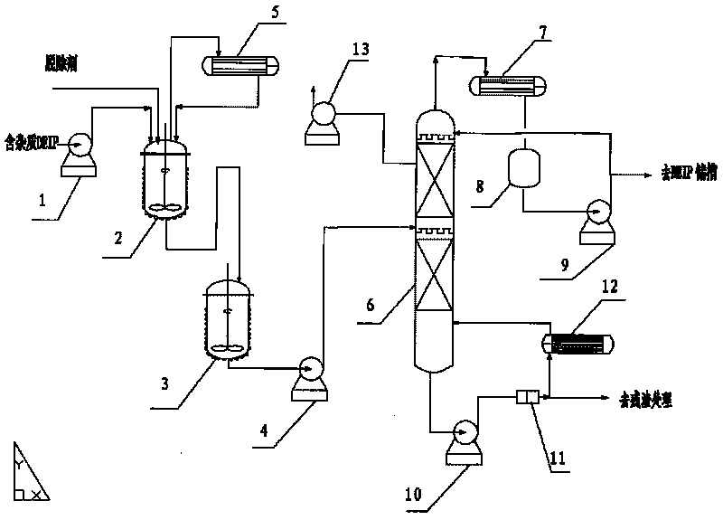
The invention relates to a method for purifying cyclic solvent in producing TDI, particularly relates to the case that if the abnormal condition that group impurities containing -NCO such as TDI, CI-TDI, m-CBC and the like are carried by the cyclic solvent DEIP occurs in producing toluene diisocynate (TDI) by a heavy solvent phosgene method, the -NCO group impurities react with TDA and phosgene in a photochemical process to lower TDI yield and generate urea and acid amides residual substances to lead to the problem that production is stopped to clean away obstruction due to the blocking of pipelines and device. The invention uses a processing method of reacting PEG or C2H5OH with -NCO group impurities, adopts rectification to separate the generated heavy components from DEIP to obtain pure DEIP at the tower top to return to a storing bank of the cyclic solvent, and the tower bottom obtains the reacted NCO components and original heavy component residual removal system, thus ensuring smooth operation of the device.
Description
Technical field [0001] The invention relates to a method for purifying circulating solvents in TDI production, in particular to the production of toluene diisocyanate by heavy solvent phosgene method, if there is entrainment of TDI, benzyl chlorotoluene diisocyanate (Cl-TDI), m -Ethyl benzoyl chloride (CBC) and other impurities containing -NCO group will react with TDA and phosgene in the photochemical process when the -NCO group impurities occur, which reduces the yield of TDI and produces The residues of urea and amides cause problems such as blocking pipelines and equipment and need to stop production to clean up the blockages. The present invention uses an external removal agent polyethylene glycol PEG (HO (C 2 H 4 O) n H) or absolute ethanol (C 2 H 5 OH) and -NCO group impurity reaction treatment method, using rectification to separate the heavy components and DEIP, the pure DEIP is obtained at the top of the tower and returned to the circulating solvent storage tank, and th...
Claims
Login to View More Application Information
Patent Timeline
 Patent Type & AuthorityApplications(China)
IPC IPC(8): C07C265/14C07C263/10
Inventor谈明传梁睿渊毕荣山耿天奇
Owner甘肃银光聚银化工有限公司