Preparation method of fiber metal matrix composite broadband light and slim type radar wave camouflage coating

A fiber metal, radar wave technology, applied in the direction of metal layered products, coatings, adhesive types, etc., can solve the problems of low mechanical properties of absorbing materials, low absorbing properties of coatings, uneven surface density, etc. Achieve the effect of low production cost, high wave absorbing performance and uniform surface density

Active Publication Date: 2010-04-28
江苏万华拓谷新材料科技有限公司
View PDF1 Cites 24 Cited by
  • Summary
  • Abstract
  • Description
  • Claims
  • Application Information

AI Technical Summary

Problems solved by technology

[0006] In order to overcome the uneven distribution of each component material in the wave-absorbing coating in the prior art, the surface density is uneven, the absorption frequency band is narrow, the coating has low wave-absorbing performance, and the wave-absorbing Due to the lack of low mechanical properties of the material, the present i

Method used


Image

  • Preparation method of fiber metal matrix composite broadband light and slim type radar wave camouflage coating
  • Preparation method of fiber metal matrix composite broadband light and slim type radar wave camouflage coating
  • Preparation method of fiber metal matrix composite broadband light and slim type radar wave camouflage coating

Examples


Embodiment 1

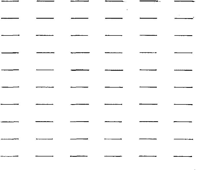
[0029] Take a 300×300×5mm aluminum plate and polish it with sandpaper, scrub it with acetone after polishing, and apply 5% aminosilane coupling agent KH-550 diluted with 95% alcohol on the aluminum plate; take a number of 10μm in diameter and 1cm in length Put the polyacrylonitrile-based carbon fiber into the adhesive solution to make the surface of the carbon fiber evenly dipped in the adhesive; adopt a column-type horizontal arrangement with a vertical spacing of 1 cm and a horizontal spacing of 1 cm (such as figure 1 As shown), a plurality of carbon fibers are evenly bonded on the surface of the aluminum plate to form a carbon fiber layer; the resulting aluminum plate with the carbon fiber layer is dried for 2.5h; The mixed solvent mixed at a volume ratio of 6:4 was added to 400g of modified spherical carbonyl iron powder, stirred evenly and then left to stand for 30min, and 106.24g of epoxy resin and 2.25g of curing agent D-4003 were added to the mixture, and then used Cut...

Embodiment 2

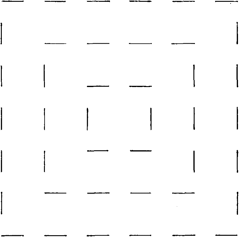
[0031] Carbon fibers are arranged according to figure 2 As shown in the "back" font arrangement, the rest of the preparation process is the same as in Example 1, and the number of the prepared wave-absorbing coated board is 8088, such as Figure 5 Shown is the reflectivity test curve of 8088 absorbing coated board, surface density 3kg / m 2 , the radar wave reflectivity is less than -7.62dB in the 8-18GHz frequency band.


PUM

PropertyMeasurementUnit
Thicknessaaaaaaaaaa
Areal densityaaaaaaaaaa
Thicknessaaaaaaaaaa

Abstract

The invention relates to a preparation method of fiber metal matrix composite broadband light and slim type radar wave camouflage coating. Coupling agent diluted by alcohol is coated on a metal plate, a plurality of polyacrylonitrile-based carbon fiber which has a diameter of 5-15 mu m, a length less than or equal to 1cm, and binder coated on the surface are uniformly adhered on the surface of the metal plate with both the longitudinal interval and the transverse interval being 0.5-1.5cm to form a carbon fiber layer and be dried for 2-4 hours, absorbing painting is sprayed on the carbon fiber layer in plural times to form an absorbing coating to be solidified for 5 hours in a baking oven of 60 DEG C to obtain the product. The invention adopts a multi-row transverse uniform arrangement of the carbon fiber having microwave scattering characteristic so as to absorb frequency bandwidth, and the absorbing coating has low density, high mechanical property, reflectivity within 8-18GHz being less than negative 8dB, strong absorbing performance as a whole, good camouflage effect, and high applicability to various weapons and military supplies and aerospace aircraft having high requirement on surface density.

Description

technical field [0001] The invention relates to a stealth material, in particular to a preparation method of a fiber metal matrix composite radar wave stealth coating with broadband light-weight stealth properties. Background technique [0002] The development of modern information-based military technology puts forward higher requirements for the survivability of weapons on the battlefield. The invisibility of military equipment is an inevitable trend in the development of weapons in our country and even in the world. Coating-type stealth materials have been widely concerned and applied to specific weapon models because of their simple process and the ability to meet the needs of various types of equipment. They have played an important role in the stealth of equipment in our country. With the development of modern military technology, higher requirements are put forward for coating-type stealth materials, namely: thin coating, wide frequency band, low density and high str...

Claims


Application Information

Patent Timeline
IPC IPC(8): G12B17/02B32B15/14C09D163/00C09D5/32B05D1/38C09J163/00
Inventor 夏益陆泳夏钢锋江立华樊飞跃孙毅赵虎
Owner 江苏万华拓谷新材料科技有限公司
Why Eureka
Try Eureka