Method for manufacturing internal conducting rod of large-scaled high-frequency resonant cavity

A high-frequency resonant cavity and manufacturing method technology, applied in cable/conductor manufacturing, manufacturing tools, circuits, etc., can solve the problems affecting the manufacturing level of the inner conductive rod, insufficient welding depth, tin pad tube falling off, etc. And the shape error is small, the performance is improved, and the vacuum index is good.

Active Publication Date: 2010-04-28
INST OF MODERN PHYSICS CHINESE ACADEMY OF SCI
View PDF0 Cites 12 Cited by
  • Summary
  • Abstract
  • Description
  • Claims
  • Application Information

AI Technical Summary

Problems solved by technology

At present, when the inner conductive rod is manufactured by conventional welding methods, due to defects such as welding deformation, insufficient welding depth, and tin solder coil tube falling off, the manufacturing level of the inner conductive rod is directly affected, and it is even easy to be scrapped midway.

Method used


Image

  • Method for manufacturing internal conducting rod of large-scaled high-frequency resonant cavity
  • Method for manufacturing internal conducting rod of large-scaled high-frequency resonant cavity
  • Method for manufacturing internal conducting rod of large-scaled high-frequency resonant cavity

Examples


Embodiment Construction

[0023] Below in conjunction with the preferred embodiment shown in accompanying drawing, be described in further detail:

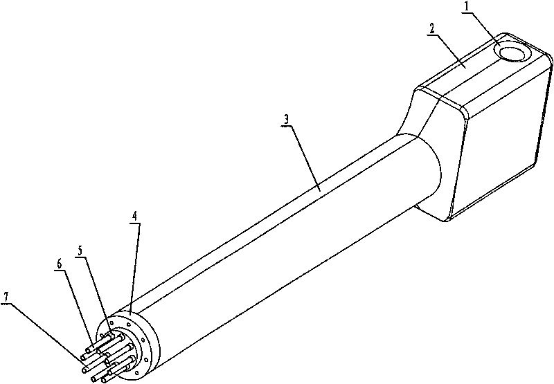
[0024] See figure 1 , 2 , 3, 4, 5, the manufacturing method of the conductive rod in the large-scale high-frequency resonant cavity is characterized in that it includes the following steps:

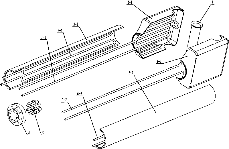
[0025] (1), the oxygen-free copper tube 3 with the machining allowance left on the outer surface and the inner surface processed to the required size is divided into two half tubes 3-1, 3-2 by wire cutting along the axis;

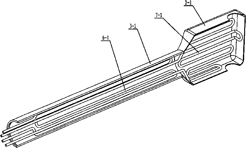
[0026] (2) Form the oxygen-free copper semi-square boxes 2-1 and 2-2 at the head of the inner conductive rod with simple moulds. In order to avoid ignition, pay special attention to the shape of the rounded corners, and then weld them with argon arc welding Penetrate the joints, and repair the joint surfaces of the oxygen-free copper half-square boxes 2-1, 2-2 and the semi-circular holes;

[0027] (3), on the platform, weld oxygen-free copper ha...


PUM


Abstract

The invention mainly relates to a method for manufacturing an internal conducting rod of a large-scaled high-frequency resonant cavity. The method comprises the following steps of: welding an oxygen free copper semi-tube and a semi-box into a whole on a platform; soldering cooling coils on the inner walls of the semi-tube and the semi-box; welding a tube sleeve and an end plate, and performing leakage detection; closely clamping a welding piece of two semi-tubes and semi-boxes by a clamping ring, and putting the welding piece of the end plate and the tube sleeve on the end head of the splicing piece; by using vacuum electric beam welder, spot welding the splicing pieces into one body, removing the clamping ring, using the vacuum electric beam welder again to achieve full penetration of weld of seams between the two semi-tubes and between the two semi-tubes and the end head; under water cooling, welding seams between the two semi-boxes and between the semi-boxes and a drift tube; welding seams between the cooling coil and the tube sleeve, and performing leakage detection; fine finishing the internal conducting rod; and finally mechanically polishing the outer surface of the internal conducting rod. The internal conducting rod of the large-scaled high-frequency resonant cavity, which is manufactured by the novel process, has the advantages of small surface resistance, good conducting performance, high cooling efficiency, good stability, small errors of dimensional size and shape, and good vacuum indexes and the improved performance of the whole high-frequency resonant cavity.

Description

Technical field: [0001] The present invention mainly relates to the technical field of a new technology for manufacturing a conductive rod in a core part of a large-scale high-frequency resonant cavity, especially a method for manufacturing a conductive rod in a large-scale high-frequency resonant cavity. Background technique: [0002] The manufacturing level of the conductive rod in the high-frequency resonant cavity is one of the keys that affect the performance parameters of the cavity. The inner conductive rod carries tens of thousands of volts of high-frequency radio frequency voltage, and its stability and reliability are very important to the resonant cavity. Therefore, whether the processing quality of the inner conductive rod can be guaranteed through a good machining process depends on the quality factor and resonance of the resonant cavity. frequency stability. At present, when conventional welding methods are used to manufacture inner conductive rods, defects su...

Claims


Application Information

Patent Timeline
Patent Type & Authority Applications(China)
IPC IPC(8): H01B13/00H05H7/18B23K15/00
Inventor 张小奇张斌王文进石爱民徐大宇李学敏孙国平李寿陆
Owner INST OF MODERN PHYSICS CHINESE ACADEMY OF SCI
Why Eureka
Try Eureka