Driving micro pump of photoinduced bending film

A light-induced bending and driving technology, applied in the direction of pumps, pump components, variable capacity pump components, etc., can solve the problems of slow heat dissipation, limited performance, low operating frequency, etc.

Active Publication Date: 2010-05-19
FUDAN UNIV
View PDF0 Cites 17 Cited by
  • Summary
  • Abstract
  • Description
  • Claims
  • Application Information

AI Technical Summary

Problems solved by technology

The piezoelectric vibrator can withstand low voltage, small deformation, and relatively weak carrying capacity; the electrostatic type requires a high voltage, often hundreds of volts, and the electrostatic driving force is usually small, and the displacement of the vibrating film is small, the maximum is only about The electromagnetic type is mainly limited by the difficulty of making miniature electromagnetic coils, and most electromagnetic devices require the current wires to be perpendicular to the moving parts, which is difficult for the planar manufacturing technology of silicon materials; thermopneumatic and Due to the influence of the thermal characteristics of the gas, the heat flow ty

Method used


Image

  • Driving micro pump of photoinduced bending film
  • Driving micro pump of photoinduced bending film
  • Driving micro pump of photoinduced bending film

Examples


Embodiment 1

[0016] This embodiment is a micropump with a valve structure.

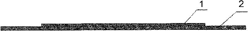
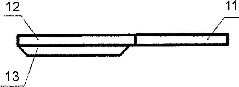
[0017] please see figure 1 As shown, the pump membrane 3 is composed of two layers, the upper layer 1 is made of photobending material, the lower layer 2 is made of flexible polymer material, and the upper layer and the lower layer are bonded by an adhesive. Because if the photobending material is fixed around, its photobending ability will be lost. Therefore, the area of ​​the upper layer of the pump membrane is designed to be smaller than that of the lower layer. It is a local composite, and the boundary of the lower layer is fixed. Irradiating the upper layer of photobending material will cause The deformation of the upper layer material, and then drives the deformation of the lower layer material.

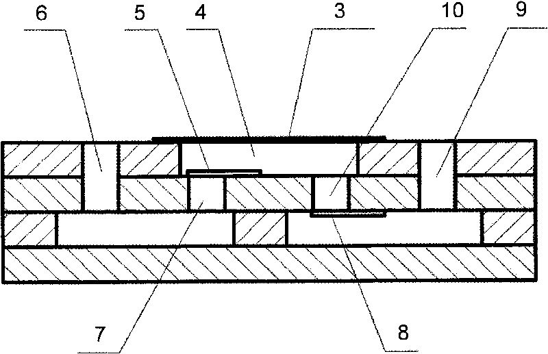
[0018] please see figure 2 As shown, the pump membrane is located at the top of the pump chamber 4, and the deformation of the pump membrane 3 leads to changes in the volume and pressure of the pump chamber. Wh...

Embodiment 2

[0021] This embodiment is a micropump adopting a valveless structure.

[0022] When the ultraviolet light is irradiated, the driving membrane is displaced upward, so that the volume of the pump cavity 4 increases and the pressure decreases. The flow into the pump chamber from the diffusion input port (water inlet 7) is greater than the flow rate from the shrink tube output port (water outlet 10) into the pump chamber, thus generating a net water intake, and the liquid is pumped into the pump chamber; when visible light is irradiated, the membrane is driven When the downward displacement resets, the volume of the corresponding pump chamber 4 decreases and the pressure increases. The original contraction tube becomes a diffuser tube, and the original diffuser tube becomes a contraction tube, and the flow out from the diffuser tube, i.e., the water outlet 10, is more than that from the contraction tube, i.e., the water inlet 7, thus producing a net water output, and the liquid is...

Embodiment 3

[0024] This embodiment is a micropump adopting a cascaded pump structure.

[0025] In view of the bending characteristics of the pump membrane in the present invention, it can be further made into the form of a cascade pump. please see Figure 5 As shown, the water outlet of the previous stage pump chamber 4 is communicated with the water inlet of the rear stage pump chamber, that is, an intermediate chamber is opened to communicate. When the pump membrane 3 of the forward pump is irradiated with ultraviolet light, and the pump membrane 3 of the backward pump is irradiated with visible light, the water inlet valve 5 of the previous pump is opened, the water outlet valve 8 is closed, and the water inlet valve 5 of the rear pump is closed. When the water outlet valve 8 is opened, the previous pump chamber absorbs water, and the latter pump chamber drains. Conversely, when the forward pump membrane 3 is irradiated with visible light and the rear pump membrane 3 is irradiated wi...


PUM


Abstract

The invention discloses a driving micro pump of a photoinduced bending film, which belongs to the technical field of micro mechanics. The micro pump mainly comprises a pump film, a pump cavity, an inlet, an outlet and the like, wherein the pump film of the micro pump is formed by partially compounding a photoinduced bending deforming material layer and a flexible polymer material layer; and the pump film periodically heaves and restores by periodically irradiating ultraviolet light and visible light. The driving micro pump has the advantages of simple structure and process, low power consumption, easy operation and control and long service life.

Description

technical field [0001] The invention belongs to the technical field of micro-mechanics, and in particular relates to a micropump driven by a light-induced bending film. Background technique [0002] The micro-flow system can accurately detect and control the flow rate of microliters per minute. At the same time, due to its small size, it can reduce the invalid volume in the micro-flow system, reduce energy consumption and reagent consumption, and has a fast response. Among them, as an important micro-actuator, the micro-pump can be widely used in drug delivery, DNA synthesis, micro-fluid supply and precise control, chip cooling system, micro-dialysis, micro-propulsion and micro-satellite, etc. as the core part of the system micropump. At present, there are more thin-film compression micropumps, and its flow control is realized by driving the reciprocating motion of the membrane to cause the volume change of the pump cavity. The driving principles of the driving film includ...

Claims


Application Information

Patent Timeline
IPC IPC(8): F04B43/02F04B53/10
Inventor 俞燕蕾朱玉田李晓英章园园陈茂林邢星黄海涛刘恒
Owner FUDAN UNIV
Why Eureka
Try Eureka