
Method for manufacturing microstructure fiber

A technology of a microstructure optical fiber and a manufacturing method, which is applied in the directions of cladding optical fiber, optical waveguide light guide, etc., can solve the problems of complex manufacturing process and low stability, and achieve the effects of simple process, reduced manufacturing cost, and reduced manufacturing process.

Inactive Publication Date: 2010-05-19
UNIV OF ELECTRONIC SCI & TECH OF CHINA
View PDF0 Cites 24 Cited by
  • Summary
  • Abstract
  • Description
  • Claims
  • Application Information

AI Technical Summary

Problems solved by technology

Although the current production method of photonic crystal fiber preform is relatively mature, the production process is complicated and the stability is not high.

Method used


Image

  • Method for manufacturing microstructure fiber
  • Method for manufacturing microstructure fiber
  • Method for manufacturing microstructure fiber

Examples


Embodiment Construction

[0022] The present invention will be further described below in conjunction with the accompanying drawings and specific embodiments.

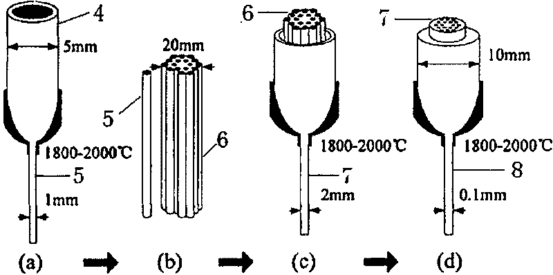
[0023] Such as Figure 4 Shown, a kind of manufacturing method of microstructure optical fiber comprises the following steps:

[0024] A. If Figure 4 As shown in (a), select a quartz or crystal fiber rod ① with a diameter of 10-20mm. Crystal fiber rod ① can use sapphire rod, sapphire hardness is very high. The diameter of the quartz or crystal fiber rod can be selected arbitrarily, and the optimum diameter range is 10-20 mm, and the diameter selected in this embodiment is 10 mm.

[0025] B. If Figure 4 As shown in (b), the corresponding processing conditions of the laser are set, and radial holes are drilled in the selected quartz or crystal fiber rod. The laser processing can use a near-ultraviolet laser or a femtosecond laser. Near-ultraviolet lasers, whose output laser wavelength range is in the near-ultraviolet spectral region (2000...


PUM

PropertyMeasurementUnit
Diameteraaaaaaaaaa

Abstract

The invention relates to a method for manufacturing a microstructure fiber. The method comprises the following steps: A, selecting a quartz or crystal fiber rod with the diameter of between 10 and 20mm; B, setting processing conditions corresponding to a laser, and punching the selected quartz or crystal fiber rod in the radial direction; and C, drawing wires under a high-temperature condition of between 1,800 and 2,000 DEG C to manufacture the microstructure fiber. The method has the advantages of reducing manufacture processes, reducing manufacturing cost, and improving the stability of achievements. The advantages of the method are reflected in that: (1) materials of preform rods have a wider selection range, and can be doped materials or undoped materials; (2) the fiber is not formed by accumulation, so collapse is avoided during wire drawing; (3) the fiber is molded once without accumulation-wire drawing repeatedly; (4) the method has simple process and stable shape, and can be manufactured in batch; and (5) end surfaces of a finished product can be hexagonal shapes, honeycomb shapes, can also be regular circles, squares and the like, so that the type characteristics of the fiber can be changed correspondingly.

Description

technical field [0001] The invention relates to the technical field of microstructured optical fibers, in particular to a method for manufacturing microstructured optical fibers. Background technique [0002] At present, the common micro-structured fiber (Micro-structured Fiber) is mainly photonic crystal fiber (Photonic Crystal Fiber, PCF). Photonic crystal fiber, also known as holey fiber (HolyFiber), was first proposed by Russell et al. in 1992. It is a two-dimensional photonic crystal with line defects. The optical fiber cladding is composed of regularly distributed air holes arranged in a hexagonal microstructure; the fiber core is composed of quartz or air holes to form a line defect, which uses its ability to localize light to confine light to propagate in the fiber core. Since the introduction of air holes in the cladding can obtain a large refractive index ratio that cannot be achieved by traditional optical fibers, and changing the size and arrangement of the air...

Claims


Application Information

Patent Timeline
IPC IPC(8): G02B6/02
Inventor 冉曾令饶云江俞晓婧
Owner UNIV OF ELECTRONIC SCI & TECH OF CHINA
Learn More