Double-chamber alga microbial fuel cell and method thereof for treating waste water and realizing zero carbon emission

A fuel cell and waste water treatment technology, applied in biochemical fuel cells, fuel cells, biological water/sewage treatment, etc., to achieve the effects of easy operation, simple invention, and zero carbon emissions

Active Publication Date: 2010-06-02
HARBIN INST OF TECH
View PDF0 Cites 50 Cited by
  • Summary
  • Abstract
  • Description
  • Claims
  • Application Information

AI Technical Summary

Problems solved by technology

[0005] The purpose of the present invention is in order to solve existing microbial fuel cell and can produce a large amount of CO in the process of treating waste water 2 problems, and then provide a double-chamber algae microbial fuel cell and its method for treating wastewater to achieve zero carbon emissions

Method used


Image

  • Double-chamber alga microbial fuel cell and method thereof for treating waste water and realizing zero carbon emission
  • Double-chamber alga microbial fuel cell and method thereof for treating waste water and realizing zero carbon emission
  • Double-chamber alga microbial fuel cell and method thereof for treating waste water and realizing zero carbon emission

Examples


specific Embodiment approach 1

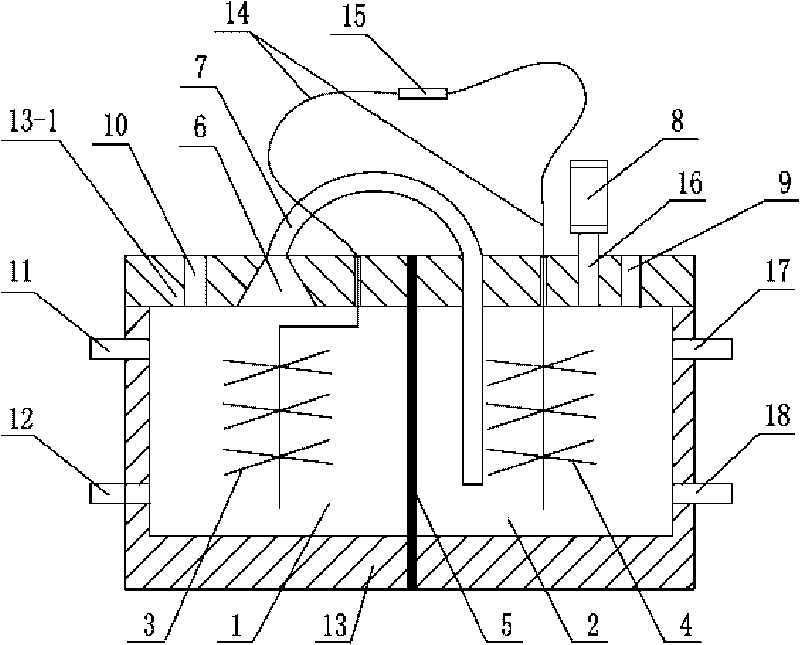
[0010] Specific implementation mode one: combine figure 1 Describe this embodiment, the double-chamber algae microbial fuel cell of this embodiment is made up of reactor casing 13, lead wire 14, external circuit 15, anode 3, cathode 4, cation exchange membrane 5, air duct 7 and gas collection device 8, The cation exchange membrane 5 is vertically arranged in the reactor casing 13, and the inside of the reactor casing 13 forms an anode chamber 1 and a cathode chamber 2, the anode 3 is arranged in the anode chamber 1, and the cathode 4 is arranged in the anode chamber 1. In the cathode chamber 2, the two ends of the wire 14 are connected to the anode 3 and the cathode 4 through the upper cover plate 131 of the reactor box 13, and the external circuit 15 is arranged outside the reactor box 13 and connected to the wire 14 , the upper cover plate 13-1 of the reactor box 13 above the anode 3 has a gas collection chamber 6, one end of the air guide pipe 7 is in sealing communication ...

specific Embodiment approach 2

[0011] Specific implementation mode two: combination figure 1 Describe this embodiment, the difference between this embodiment and specific embodiment one is: the anode 3 is carbon cloth, carbon paper, carbon felt, carbon brush, activated carbon particles, graphite plate, graphite particles, stainless steel plate, stainless steel mesh, Titanium plate or titanium mesh. Other compositions and connections are the same as in the first embodiment.

specific Embodiment approach 3

[0012] Specific embodiment 3: The difference between this embodiment and specific embodiment 2 is that the carbon brushes are pretreated, and the pretreatment method of the carbon brushes is as follows: heat the carbon brushes at 450°C for 30 minutes, Then cool to room temperature, and put the carbon brush into 10% H 2 SO 4 Soak in the solution for 10 minutes, then put it into a NaOH solution with a mass concentration of 10% for neutralization, and then wash it with distilled water. Other compositions and connections are the same as in the first embodiment.

[0013] Specific implementation mode four: combination figure 1 Describe this embodiment, the difference between this embodiment and specific embodiments 1 to 3 is: the cathode 4 is carbon cloth, carbon paper, carbon felt, carbon brush, activated carbon particles, graphite plate, graphite particle, stainless steel plate, stainless steel mesh , titanium plate or titanium mesh. Other compositions and connections are the ...


PUM


Abstract

The invention discloses a double-chamber alga microbial fuel cell and a method thereof for treating waste water and realizing zero carbon emission, which relates to a microbial fuel cell and a method for treating waste water. The invention solves the problem that the traditional microbial fuel cell can generate a large amount of CO2 in the process of treating waste water. In the invention, a cation exchange membrane is vertically arranged in a box body of a reactor; an anode chamber and a cathode chamber are formed in the box body of the reactor; an anode is arranged in the anode chamber; a cathode is arranged in the cathode chamber; leads are connected with the anode and the cathode; one end of a gas duct is hermetically connected with a gas collecting chamber, and the other end of the gas duct is arranged at the bottom of the cathode chamber; and a gas collecting device is hermetically installed at a gas outlet. The method comprises the following steps: (1) starting the reactor; and (2) introducing the waste water into the cathode chamber and the anode chamber, catabolizing organic matters by microbes at room temperature, simultaneously obtaining electrical energy, and introducing the CO2 generated in the anode chamber into the cathode chamber to be used by the alga at the cathode for photosynthesis. The invention realizes zero emission of CO2 and simultaneously can recover electrical energy, thereby really changing waste into resources.

Description

technical field [0001] The invention relates to a microbial fuel cell and a method for treating waste water. The invention realizes zero-carbon discharge of waste water treatment and belongs to the field of waste water biological treatment reuse and resource utilization. Background technique [0002] The issue of global warming is receiving great attention from the international community, the global CO 2 The call to reduce emissions is growing louder. On February 16, 2005, the "Kyoto Protocol", which aims to limit global greenhouse gas emissions, held an agreement entry into force ceremony in Kyoto, Japan. Currently, 141 countries have ratified the agreement. The agreement requires industrialized countries to comply with verifiable limits on greenhouse gas emissions and to achieve an average reduction of emissions to 5% below 1990 levels between 2008 and 2012. The United Nations Climate Change Conference in 2007 adopted the "Bali Roadmap" for negotiations on the post-201...

Claims


Application Information

Patent Timeline
Patent Type & Authority Applications(China)
IPC IPC(8): H01M8/16H01M4/96H01M8/06C02F3/32C02F3/34
CPCY02E60/527Y02E60/50
Inventor 冯玉杰刘佳王鑫
Owner HARBIN INST OF TECH
Why Eureka
Try Eureka