
Cavity adjustment system and cavity adjustment method of laser resonant cavity

A technology of laser resonator and cavity adjustment, which is applied in the direction of lasers, laser components, laser components, etc., and can solve the problems of reduced accuracy and repeatability of human observation and judgment, decreased accuracy and repeatability of cavity adjustment, and aberration detection The system is expensive and other issues

Active Publication Date: 2011-09-28
NAT UNIV OF DEFENSE TECH
View PDF1 Cites 0 Cited by
  • Summary
  • Abstract
  • Description
  • Claims
  • Application Information

AI Technical Summary

Problems solved by technology

However, in the actual tuning process, due to the subjectivity of human eye observation, the symmetry of the interference fringes cannot be quantitatively judged. Therefore, different operators have subjective uncertainty in judging whether the interference fringes are symmetrical, which will lead to The accuracy and repeatability of the
In addition, environmental vibration and air disturbance will cause image blurring and throughput in the interference fringe image, which further reduces the accuracy and repeatability of human observation and judgment.
[0005] Chinese patent document No. CN100555772C discloses a cavity adjustment method based on an autocollimation feedback optical path, which can realize high-precision adjustment of confocal unstable cavity, but this method requires the use of an aberration detection system, the aberration detection The system is relatively expensive, and this method is only suitable for the adjustment of unstable chambers, which has certain limitations

Method used


Image

  • Cavity adjustment system and cavity adjustment method of laser resonant cavity
  • Cavity adjustment system and cavity adjustment method of laser resonant cavity
  • Cavity adjustment system and cavity adjustment method of laser resonant cavity

Examples


Embodiment 1

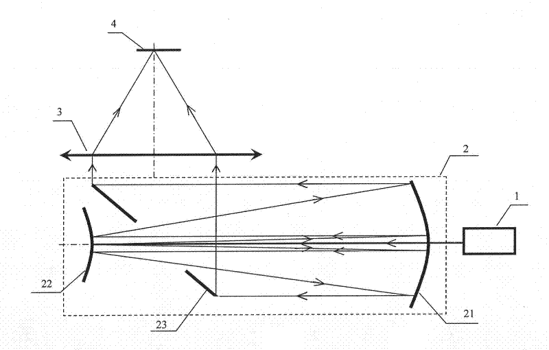
[0093] a kind of like Figure 5 The present invention shown is used for the cavity tuning system and the cavity tuning method of positive-branched confocal unstable cavity. The radius of curvature of the mirror 21 is 3m, and its effective aperture is 50mm. The radius of curvature of the convex mirror 22 is -1m, and the length of the cavity is 1m; the major axis radius of the elliptical hole of the output coupling mirror 23 is 9.2mm, and the minor axis radius is 6.5mm; the lens The focal length of 3 is 500mm; the CCD camera 7 has a frame rate of 15fps and a resolution of 1392×1040; the transmittance of the attenuator 11 is continuously adjustable from 99.9% to 0.

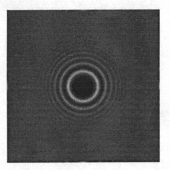
[0094] After completing the preliminary installation and debugging according to the steps 1-6 described in the specific implementation mode of the above-mentioned unstable cavity tuning, the obtained tuning interference fringe pattern is as follows Figure 9 shown.

[0095] Then, according to the processing flow of...

Embodiment 2

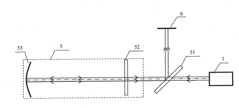
[0132] a kind of like Figure 8 The present invention shown is used for the cavity tuning system and the cavity tuning method of the stable cavity. The structure and composition of the cavity tuning system are the same as the above-mentioned stable cavity tuning implementation. In the cavity tuning system, the reflector 53 (being a concave surface The radius of curvature of mirror) is 3m, and its effective aperture is 30mm, and output mirror 52 is a plane mirror, and the length of stable cavity cavity is 1m; Beam splitter 51 is 50% to the transmittance of guide light, reflectivity; Lens 3 The focal length is 500mm; the CCD camera 7 has a frame rate of 15fps and a resolution of 1392×1040; the transmittance of the attenuator 11 is continuously adjustable from 99.9% to 0.

[0133] After completing the preliminary installation and commissioning according to the steps 1-6 described in the specific implementation of the above-mentioned stable tune tune, the tune tune interference fr...


PUM


Abstract

The invention discloses a cavity adjustment system of a laser resonant cavity, comprising a laser for outputting guidance light, a laser resonant cavity and assistant resetting equipment. The assistant resetting equipment comprises a CCD camera, an image acquisition and processing system and data display equipment, wherein the image acquisition and processing system comprises an acquisition unit and an image processing unit; the CCD camera, the acquisition unit, the image processing unit and the data display equipment are successively connected via a data line. the laser, the laser resonant cavity and the CCD camera of the assistant resetting equipment are successively arranged along light paths. When in adjusting the cavity, guidance light emitted from the laser enters the laser resonant cavity after being attenuated by an attenuator; a light beam output after multiple round-trip is injected onto the photosurface of the CCD camera after contraction so as to form interference fringe image information; the image information is collected and processed by the image acquisition and processing system to obtain symmetry data; and finally, according to the obtained symmetry data, an endoscope in the laser resonant cavity is adjusted.

Description

technical field [0001] The invention relates to a matching component and a use method of an optical resonant cavity, in particular to an optical resonant cavity tuning system and a tuning method thereof. Background technique [0002] The laser resonator is the key device to realize laser energy extraction and output in the laser. Whether the laser resonator is collimated or not will directly affect the output beam quality and output power stability of the laser, so the laser must be installed or operated. The installation and adjustment of the resonant cavity mirror can only achieve the predetermined output index if the position of the cavity mirror meets the design requirements. [0003] Laser resonators are divided into two categories: unstable cavity and stable cavity. The output beam wavefront of the laser using the unstable cavity is spherical wave or plane wave, which is generally used for high-energy lasers; the output of the laser using the stable cavity is Gaussian ...

Claims


Application Information

Patent Timeline
Patent Type & Authority Patents(China)
IPC IPC(8): H01S3/02H01S3/086
Inventor 刘文广陈星靳冬欢王怀琛袁圣付华卫红陈金宝姜宗福
Owner NAT UNIV OF DEFENSE TECH
Learn More