Method for welding lead of diode and diode

A technology of diodes and leads, which is applied in the diode lead welding method and the field of diodes, can solve the problems of large leakage current of diodes, pollution of chips, low production efficiency, etc., achieve high withstand voltage, not easy to break down, and improve production efficiency.

Active Publication Date: 2010-06-16
GUIZHOU YAGUANG ELECTRONICS TECH
View PDF0 Cites 6 Cited by
  • Summary
  • Abstract
  • Description
  • Claims
  • Application Information

AI Technical Summary

Problems solved by technology

This welding method has complicated process, low production efficiency, high production cost and large thermal resistance.
Due to th

Method used


Image

  • Method for welding lead of diode and diode
  • Method for welding lead of diode and diode
  • Method for welding lead of diode and diode

Examples


Embodiment Construction

[0018] The diode lead welding method and the diode of the present invention will be further described in detail below in conjunction with the accompanying drawings and embodiments, but it is not used as a basis for any limitation of the present invention.

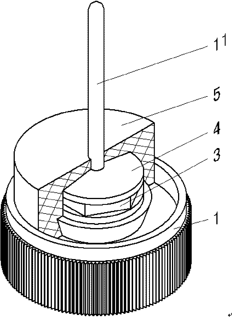
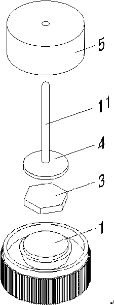
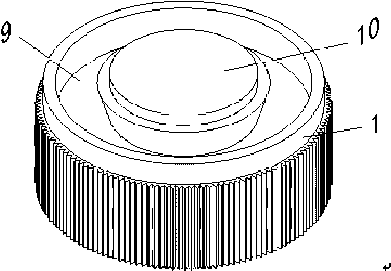
[0019] Example. A diode lead welding method. The present invention is an improvement to the existing diode lead wire welding method, and the structure of the existing diode is as follows: Figure 5 As shown, it includes a tube base 1, a copper sheet 2, a chip 3, a lead base 4, an epoxy resin sealing layer 5 and a soldering sheet 6. The structure of the present invention is as figure 1 with figure 2 shown. The method of the present invention is to place the chip 3 on the soldering station 10 of the tube base 1, then press the lead base 4 on the chip 3, and burn the lead base 4, the chip 3 and the soldering platform 10 of the tube base 1 by one-time welding. Welded together; after welding, carry out table modeling and u...


PUM


Abstract

The invention discloses a method for welding a lead of diode and a diode. The method comprises the following steps: placing a chip on a welding station of a tube seat, then pressing a lead seat on the chip, and welding the lead seat, the chip and the welding station of the tube seat together by adopting primary welding; and molding and ultrasonically cleaning the station surface after welding, and then encapsulating the whole with epoxy resin. The structure of the diode comprises the tube seat (1) which is connected with the chip (3) and the lead seat (4) in turn; and an epoxy resin sealing layer (5) is arranged outside the chip (3) and the lead seat (4). The method can simplify the welding process, improve the production efficiency and reduce the production cost; and the produced diode has the advantages of low leakage current, low thermal resistance and high voltage resistance, and is not easy to break down.

Description

technical field [0001] The invention relates to a diode, in particular to a diode lead welding method and the diode. Background technique [0002] A 50A silicon avalanche rectifier diode is used in the motor vehicle, which is mainly used to convert the alternating current generated by the motor vehicle generator into direct current for the use of the motor vehicle. In the prior art, the soldering of the diode leads is a secondary soldering process with flux added. The first soldering is to put the solder, chip, solder and copper sheet under the lead base in sequence, solder the chip on the lead base first, use bare copper for the copper, and add flux to the copper, after soldering Acid etching treatment. Then carry out the second welding. The second welding is to weld the copper sheet at the lower end of the welded lead wire and the pipe seat together, and put the welding sheet on the pipe seat for the second welding during welding. This welding method has complicated pr...

Claims


Application Information

Patent Timeline
IPC IPC(8): H01L21/50H01L21/60H01L21/58H01L21/56H01L23/488H01L23/31H01L23/13
CPCH01L24/01
Inventor 杨长福
Owner GUIZHOU YAGUANG ELECTRONICS TECH
Why Eureka
Try Eureka