Cutting assembly of wafer line cutting machine

A wire cutting machine, silicon wafer technology, applied in grinding machines, metal processing equipment, grinding/polishing equipment, etc., can solve the problems of increased swing, large surface roughness and thickness errors of slices, frequent shutdowns, etc., to prevent Axial displacement and radial runout, improve cutting efficiency, ensure the effect of continuous operation

Inactive Publication Date: 2013-11-13
HENAN UNIV OF SCI & TECH
View PDF0 Cites 0 Cited by
  • Summary
  • Abstract
  • Description
  • Claims
  • Application Information

AI Technical Summary

Problems solved by technology

Due to the structure and working principle of this machine, it has the following shortcomings: 1. The steel wire wound on the roller is single-wire stressed when the machine is working, and the diameter of the steel wire used is only 0.10 or 0.12mm, and its breaking strength is 28N Or 45N, therefore, the machine often breaks down when it is working, resulting in frequent shutdowns, and it takes at least 30 minutes to rewire, which damages the continuous operation of the machine; 2. In order to prevent or reduce the frequency of disconnection, the machine The line speed is low when working, which greatly affects the cutting efficiency; 3. Due to the spiral groove structure of the two rollers of the machine, the line used in each batch is as long as 400KM, and it is technically impossible to fix the abrasive grains on such a long steel line. Therefore, the expensive cutting fluid and silicon carbide micropowder sprayed on the surface of steel wire and silicon material can only randomly enter the slit to participate in grinding, and more than 90% flow out and be scrapped; 4. Determined by the structure and working principle, the 400KM steel wire can only be used once After passing through the slit, in addition to many broken ends, the overall tensile strength of the wire was destroyed due to corrosion and abrasion. The whole roll of steel wire recovered by the take-up roller includes at least tens of KM of new The wires are all scrapped; 5. The two rollers are arranged in parallel, so that the diameter of the roller must be greater than the diameter or height of the silicon rod or ingot to be cut, and the cutting can be carried out; the large diameter roller not only increases the manufacturing cost and power consumption, but more importantly The most important thing is that the line distance is widened and the swing of the line operation process is increased, which affects the quality of the slice; Sixth, the uncertainty of the position and angle of the silicon carbide abrasive grain entering the slit, resulting in a relatively large error in the surface roughness and thickness of the slice. Big

Method used


Image

  • Cutting assembly of wafer line cutting machine
  • Cutting assembly of wafer line cutting machine
  • Cutting assembly of wafer line cutting machine

Examples


Embodiment Construction

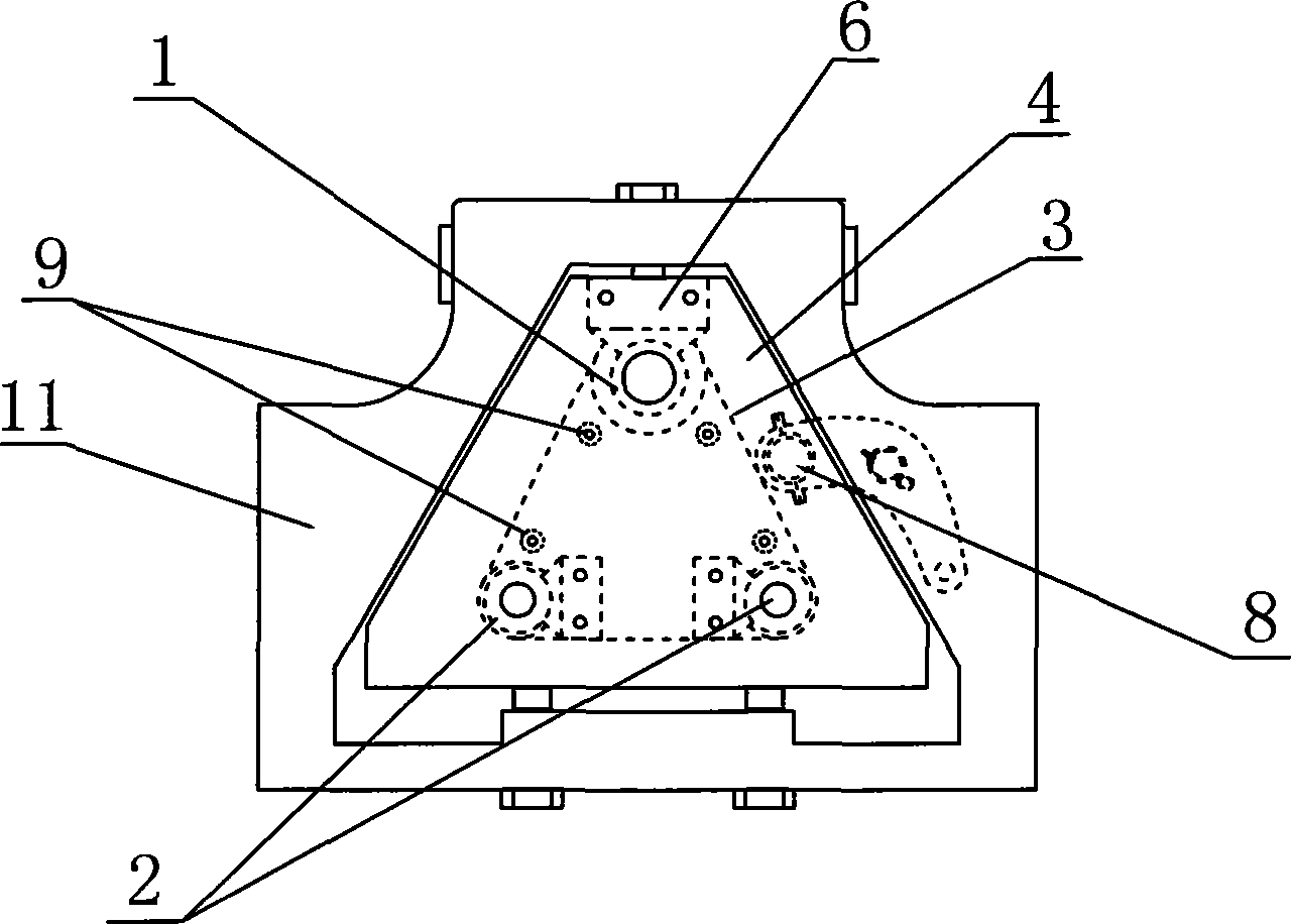
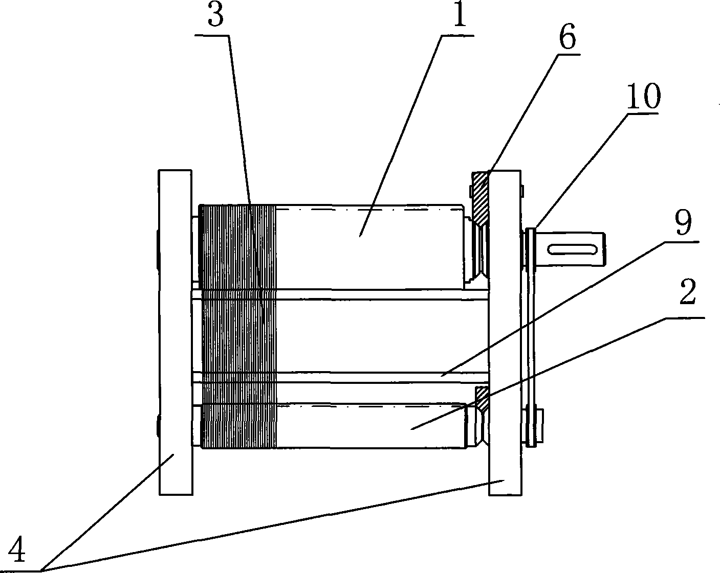
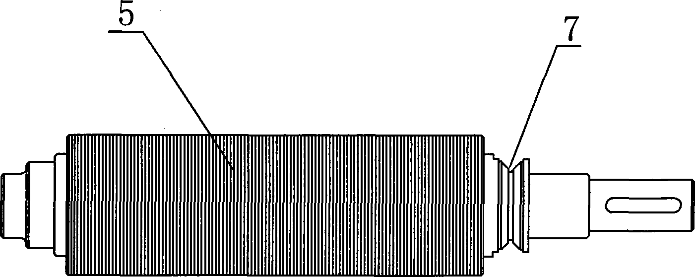
[0018] As shown in the figure, the cutting assembly of the silicon wafer wire cutting machine is mainly composed of the driving roller 1, the driven roller 2, the end plate 4 and the cutting line 3, and the driving roller 1 and the driven roller 2 are formed by the end plate 4 support, the circumference of the driving roller 1 and the driven roller 2 are respectively provided with annular wire grooves 5, and each wire groove is independent of each other and perpendicular to the axis of the rollers. The number of wire grooves on the driving roller 1 and the driven roller 2 is equal, and the distance between any two adjacent wire grooves 5 is equal. According to different specifications, the groove width of the wire groove 5 is 0.09-0.16mm, generally 0.13mm; the groove depth is 0.15-0.25mm, generally 0.2mm; the distance between two adjacent wire grooves 5 is 0.15-0.25mm , generally 0.15mm. The cutting line 3 is wound in the wire groove 5 corresponding to the position on the dri...


PUM


Abstract

The invention relates to a cutting assembly of a wafer line cutting machine, which mainly comprises a driving roller, a driven roller, an end plate and cutting lines. The driving roller and the driven roller are supported by the end plate, the peripheries of the driving roller and the driven roller are respectively provided with annular line grooves, the number of the line grooves on the driving roller is identical to the number of the line grooves on the driven roller, the distances between any two adjacent line grooves are identical, the cutting lines are wound in the line grooves of the driving roller and the driven roller and are of a ring shape, the number of the cutting lines is identical to the number of the line grooves of the driving roller and the driven roller. Due to the arrangement of hundreds of ring-shaped cutting lines, the invention greatly improves the tensile strength, reduces the line breaking rate, ensures the capability of the equipment for continuous operation and also significantly improves the linear speed, thereby greatly improving the cutting efficiency and ensuring the slice accuracy and quality.

Description

technical field [0001] The invention relates to a wire cutting machine for silicon wafers, in particular to a cutting assembly of the wire cutting machine for cutting crystal silicon wafers. Background technique [0002] With the vigorous rise of renewable, clean and pollution-free new energy strategies in the world, solar photovoltaic cell power generation projects are developing rapidly. Whether crystalline silicon is used in the electronics industry or the photovoltaic industry, the application and pricing of its end products are based on area, that is, the use form of its end products is in the form of flakes. At present, the silicon wafer wire cutting machine sold on the market carries and supports the cutting wire by two roller mechanisms respectively engraved with spiral grooves. The working principle is: pull out one end of the 400KM steel wire on the pay-off roller, Wrapped on the two rollers respectively, pulled by the rotation of the take-up roller, at the same t...

Claims


Application Information

Patent Timeline
Patent Type & Authority Patents(China)
IPC IPC(8): B24B27/06
Inventor 刘刚田曹慧敏巫滨霍银磊王珊珊刘丽娜杨晓帆许菁斐
Owner HENAN UNIV OF SCI & TECH
Why Eureka
Try Eureka