
System for vacuum drying sludge by adopting solar energy

A vacuum drying and solar energy technology, applied in dewatering/drying/concentrating sludge treatment, energy and wastewater treatment, etc., can solve the problems of large greenhouse drying area, high greenhouse construction cost, high overall cost, saving equipment investment, The effect of reducing energy consumption and compact structure

Inactive Publication Date: 2010-07-21
DONGHUA UNIV
View PDF4 Cites 8 Cited by
  • Summary
  • Abstract
  • Description
  • Claims
  • Application Information

AI Technical Summary

Problems solved by technology

[0004] Existing thermal sludge drying technology requires heat sources for drying wet sludge mainly from waste heat of boiler flue gas, direct heating and drying with auxiliary fuel or electric energy, or low-grade steam (such as steam after steam turbine has done work), using boiler waste heat Flue gas drying needs to be equipped with tail gas treatment devices; and using auxiliary fuel or electric energy to heat and dry will consume a lot of energy, so the overall cost of the above heat source supply methods is relatively high
In addition, the existing technology of using solar energy to dry sludge generally adopts the solar greenhouse drying method, but the cycle of drying sludge in a greenhouse is very long, and it usually takes more than a week to achieve the purpose of sludge drying, and the greenhouse drying covers an area of Large, the construction cost of the greenhouse is relatively high

Method used


Image

  • System for vacuum drying sludge by adopting solar energy
  • System for vacuum drying sludge by adopting solar energy
  • System for vacuum drying sludge by adopting solar energy

Examples


Embodiment Construction

[0028] Below in conjunction with specific embodiment, further illustrate the present invention. It should be understood that these examples are only used to illustrate the present invention and are not intended to limit the scope of the present invention. In addition, it should be understood that after reading the teachings of the present invention, those skilled in the art can make various changes or modifications to the present invention, and these equivalent forms also fall within the scope defined by the appended claims of the present application.

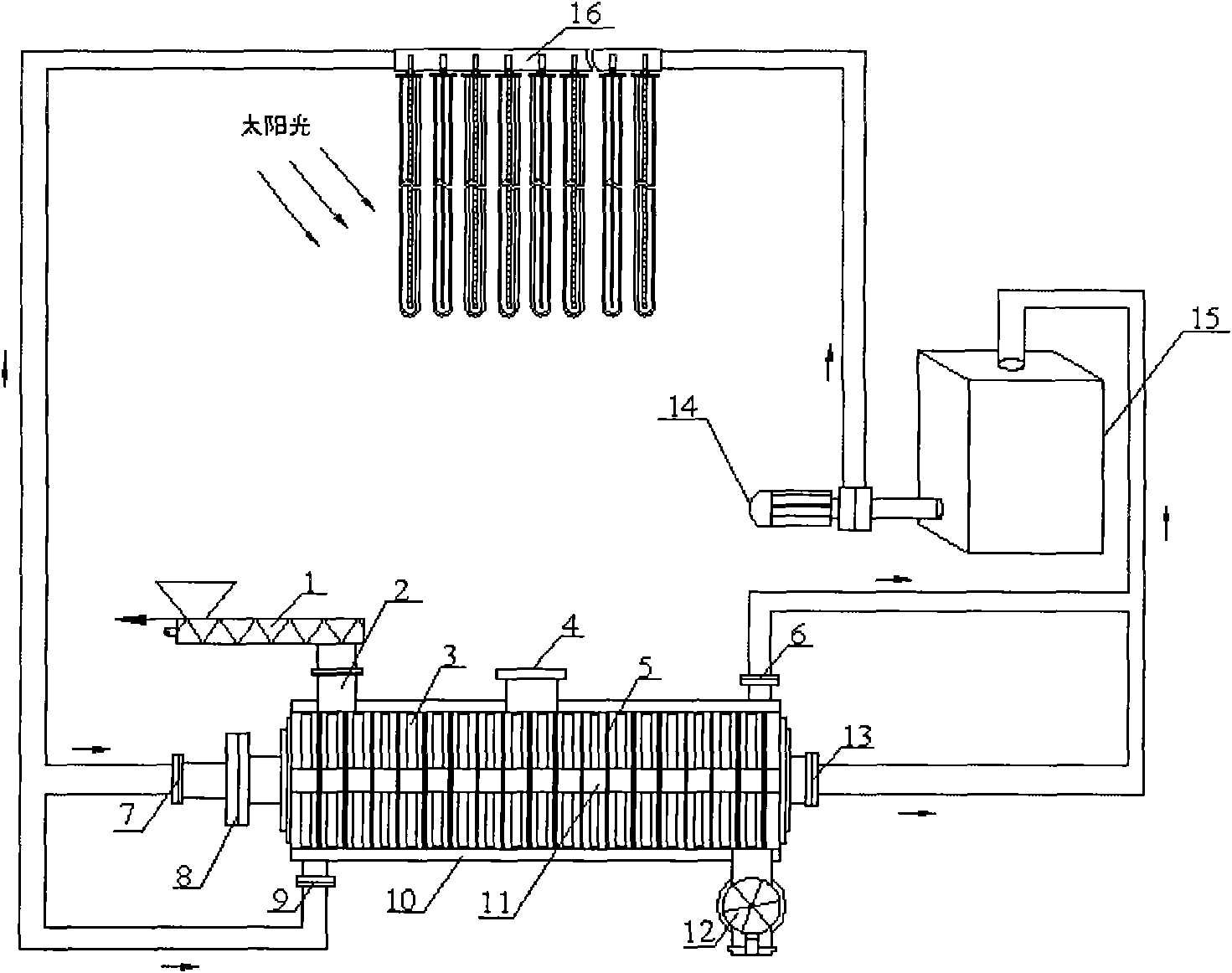
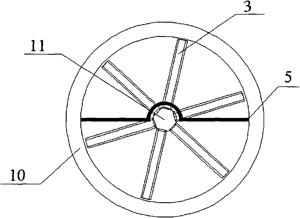
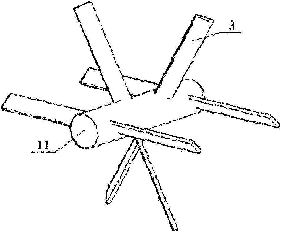
[0029] Embodiments of the present invention relate to a system for vacuum drying sludge using solar energy, such as figure 1 As shown, it includes a double-leaf inclined self-cleaning sludge vacuum continuous dryer, a solar collector, a heat transfer oil tank 15 and a heat transfer oil pump 14. The dryer has a cylindrical vacuum housing; the upper part of the vacuum housing There is a vacuum port 4, so that the absolute vacuum...


PUM


Abstract

The invention relates to a system for vacuum drying sludge by adopting solar energy, comprising a self-cleaning sludge continuous vacuum drier with inclined two blades, a solar thermal collector, a heat conducting oil tank and a heat conducting oil pump. A cylindrical vacuum casing of the drier is internally provided with a vacuum thermal axis connected to a gearing. The vacuum thermal axis is provided with multiple sets of blades which are arranged in the inclined double blades manner. Both heat conducting oil outlets of the vacuum thermal axis and the casing are connected to the heat conducting oil tank through pipelines. Both heat conducting oil inlets and the outlets of the vacuum thermal axis and the casing are connected to the solar thermal collector through the pipelines. The heat conducting oil tank and the heat conducting oil pump are connected to the solar thermal collector through the pipelines. The invention realizes the drying of the sludge by adopting the solar energy, greatly reduces energy consumption during the sludge drying and saves energy by utilizing the self-cleaning vacuum sludge drier with inclined double blades.

Description

technical field [0001] The invention relates to the technical field of harmless and resourceful treatment of solid waste, in particular to a system for vacuum drying sludge by using solar energy. Background technique [0002] With the acceleration of my country's urbanization process and the strengthening of urban infrastructure construction, the urban sewage treatment rate has gradually increased, accompanied by a large amount of excess sludge. If these sludges cannot be treated in a timely, effective and stable manner, it will bring great hidden dangers to the safety of our regional environment and people's lives. In addition, industrial processes such as papermaking, chemical industry, tanning, printing and dyeing, and dredging of rivers and lakes will also produce a large amount of sludge. The harmless treatment of sludge has become a major environmental protection problem that must be solved in the process of urban scientific development. [0003] The moisture content...

Claims


Application Information

Patent Timeline
Patent Type & Authority Applications(China)
IPC IPC(8): C02F11/12
CPCY02W10/37
Inventor 邓文义苏亚欣
Owner DONGHUA UNIV
Learn More