
Multi-optical fiber channel laser infrared gas sensor

A gas sensor and multi-fiber technology, applied in the field of infrared gas sensors, can solve the problems of strong heating, obvious delay, damage, etc., and achieve the effects of high detection sensitivity, improved integration, and good identifiability

Inactive Publication Date: 2010-09-01
无锡沃浦光电传感科技有限公司
View PDF3 Cites 1 Cited by
  • Summary
  • Abstract
  • Description
  • Claims
  • Application Information

AI Technical Summary

Problems solved by technology

But it has the following serious defects: the reaction requires oxygen to participate, that is, the oxygen content in the detected environment cannot be too low, and its detection value will be low when the oxygen content is lower than 16%; there are silicon, chlorine, When sulfur and other compounds are used, the sensor will be poisoned, the sensitivity will be seriously reduced or even completely invalid; it can only detect low combustible gas concentration, the gas concentration is too high or long-term exposure to low concentration gas will cause the sensitivity of the sensor to be greatly reduced or damaged; Slow, noticeable lag; poor stability, requires recalibration every few months
However, general laser infrared gas sensors are not suitable for combustible gas monitoring. The reason is that the infrared light source used is a quantum cascade laser, which has a large operating current and strong heat generation. It needs to use a semiconductor thermoelectric cooler to cool and stabilize the temperature. If the refrigerator fails or the sensor does not discharge heat in time, flammable and explosive gases may be ignited, resulting in catastrophic consequences

Method used


Image

  • Multi-optical fiber channel laser infrared gas sensor
  • Multi-optical fiber channel laser infrared gas sensor
  • Multi-optical fiber channel laser infrared gas sensor

Examples


Embodiment Construction

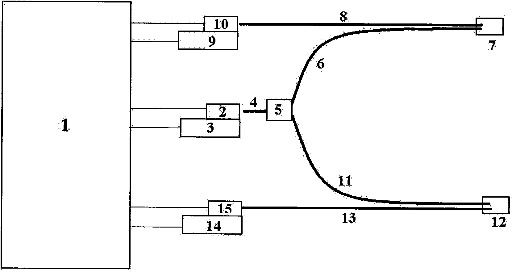
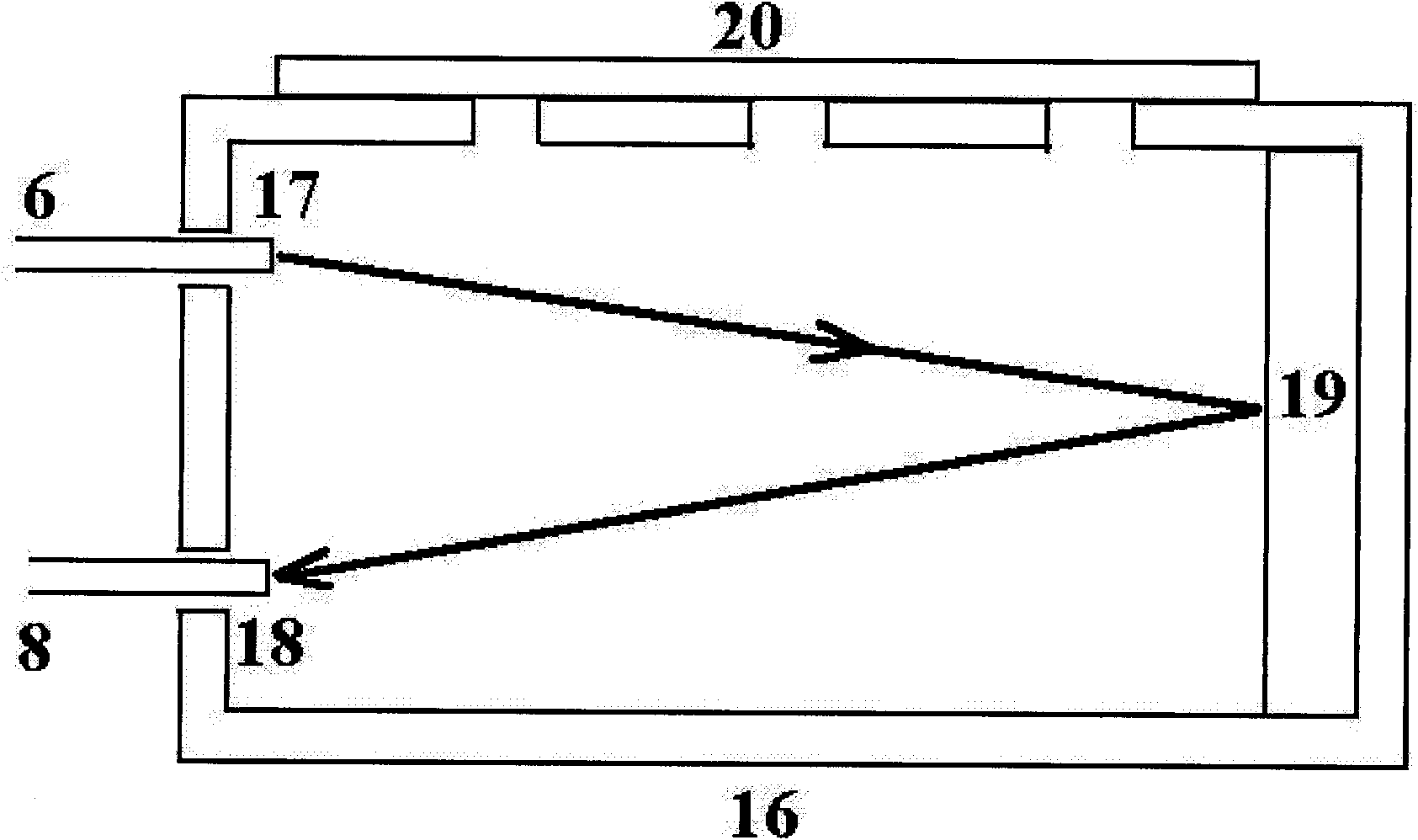
[0021] like figure 1 As shown, the multi-fiber channel (taking two fiber channels as an example) laser infrared gas sensor of the present invention includes: circuit and man-machine exchange module 1, used for power supply management, system control, phase-locked amplification, acquisition and storage of signals , analysis and reading, and human-computer interaction; the first semiconductor thermoelectric cooler 2 is connected with the circuit and the human-machine exchange module 1 for temperature control; the quantum cascade laser 3 is fixed on the first semiconductor thermoelectric cooler 2 and be connected with the circuit and the man-machine exchange module 1 for emitting infrared laser; the lens fiber 4 (the first optical fiber), near the light-emitting end of the quantum cascade laser, is used to collimate the infrared light emitted by the quantum cascade laser and Lead in optical fiber; fiber coupler 5, connect lens optical fiber 4, divide laser light into a plurality ...


PUM


Abstract

The invention discloses a multi-optical fiber channel laser infrared gas sensor comprising a circuit and man-machine exchange module, at least one semiconductor thermoelectric refrigerator, a laser, at least one infrared detector and an optical fiber probe, wherein the circuit and man-machine exchange module is used for power supply management, system control, and the phase-locking amplification, the collection, the storage, the analysis and the reading of signals as well as man-machine interaction; the semiconductor thermoelectric refrigerator is connected with the circuit and man-machine exchange module and is used for realizing temperature control; the laser is fixed on the semiconductor thermoelectric refrigerator, is connected with the circuit and man-machine exchange module, and is used for transmitting infrared laser; the infrared detector is fixed on the semiconductor thermoelectric refrigerator, is connected with the circuit and man-machine exchange module, and is used for receiving infrared laser; and the optical fiber probe is connected with the laser and the infrared detector through an optical fiber and is used for detecting a plurality of gas points to be detected. The invention can detect gas in the distance or corners with higher safety and simultaneously detect a plurality of gas measuring points, improves the integration, and lowers the cost.

Description

technical field [0001] The invention relates to an infrared gas sensor, in particular to a laser infrared gas sensor with multiple optical fiber channels. Background technique [0002] In the petrochemical industry and mineral development, there are often flammable gases such as carbon monoxide, alkanes, alkenes, and alkynes, and organic vapors such as benzene, aldehydes, and ketones. They are flammable and explosive, and pose a huge threat to production safety and environmental protection. It must be closely monitored in real time. There are mainly two types of sensors for detecting flammable gases: catalytic combustion and infrared absorption. The catalytic combustion sensor is relatively easy to design and manufacture, and the price is relatively low. But it has the following serious defects: the reaction requires oxygen to participate, that is, the oxygen content in the detected environment cannot be too low, and its detection value will be low when the oxygen content ...

Claims


Application Information

Patent Timeline
IPC IPC(8): G01N21/35G01N21/3504
Inventor 刘惠春杨耀
Owner 无锡沃浦光电传感科技有限公司
Learn More