Low-entropy mixed-fuel engine

A technology of engines and combustion chambers, which is applied in the direction of engine components, machines/engines, mechanical equipment, etc., can solve the problems of low cooling medium temperature, low heat grade, low heat grade, etc., and achieve the effect of improving the degree of load response

Inactive Publication Date: 2010-09-15
靳北彪
View PDF11 Cites 22 Cited by
  • Summary
  • Abstract
  • Description
  • Claims
  • Application Information

AI Technical Summary

Problems solved by technology

Although similar attempts have been made in the past about the so-called mixed-combustion engine, such as the international patent WO99/37904, there is no real significance. The reason is that the temperature of the cooling medium on the outer wall of the combustion chamber as mentioned above is low, and the heat grade is too low. In other words, due to the limitation of the structure of the existing internal combustion engine, the outer wall of the combustion chamber requires high cooling intensity, and the temperature of the cooling medium is low, resulting in a low grade of heat.
[0007] Although the invention patent I applied for with the application number 200810135005.X has been improved, but; first, it was limited to the structure of the existing engine at that time, and it was believed that the temperature of the cooling water in the cooling system was much lower than the temperature of the exhaust gas, so the external combustion The working medium of the internal combustion engine (that is, the cooling medium of the internal combustion engine) first passes through the pressure-bearing channel of the cylinder liner and the cylinder head to absorb heat and heat up or even vaporize, and then flows into the exhaust heat exchanger for further heat absorption, but the working medium of the external combustion engine (that is, the cooling medium of the internal combustion engine) this arrangement of flow direction is now considered to be inefficient and unreasonable; due to the improvement of the structure and materials of engine cylinders, pistons and other parts, especially due to the use of suspended pistons, in controlling external combustion On the premise that the flow rate of the working medium of the internal combustion engine (that is, the cooling medium of the internal combustion engine) improves its thermal quality, the temperature of the working medium of the external combustion engine (that is, the cooling medium of the internal combustion engine) can be close to or even exceed the temperature of the exhaust gas of the internal combustion engine before entering the atmosphere. When the temperature of the working fluid of the external combustion engine is already high, it absorbs little or no heat after passing through the exhaust heat exchanger, resulting in a high temperature of the ex

Method used


Image

  • Low-entropy mixed-fuel engine
  • Low-entropy mixed-fuel engine
  • Low-entropy mixed-fuel engine

Examples


Embodiment 1

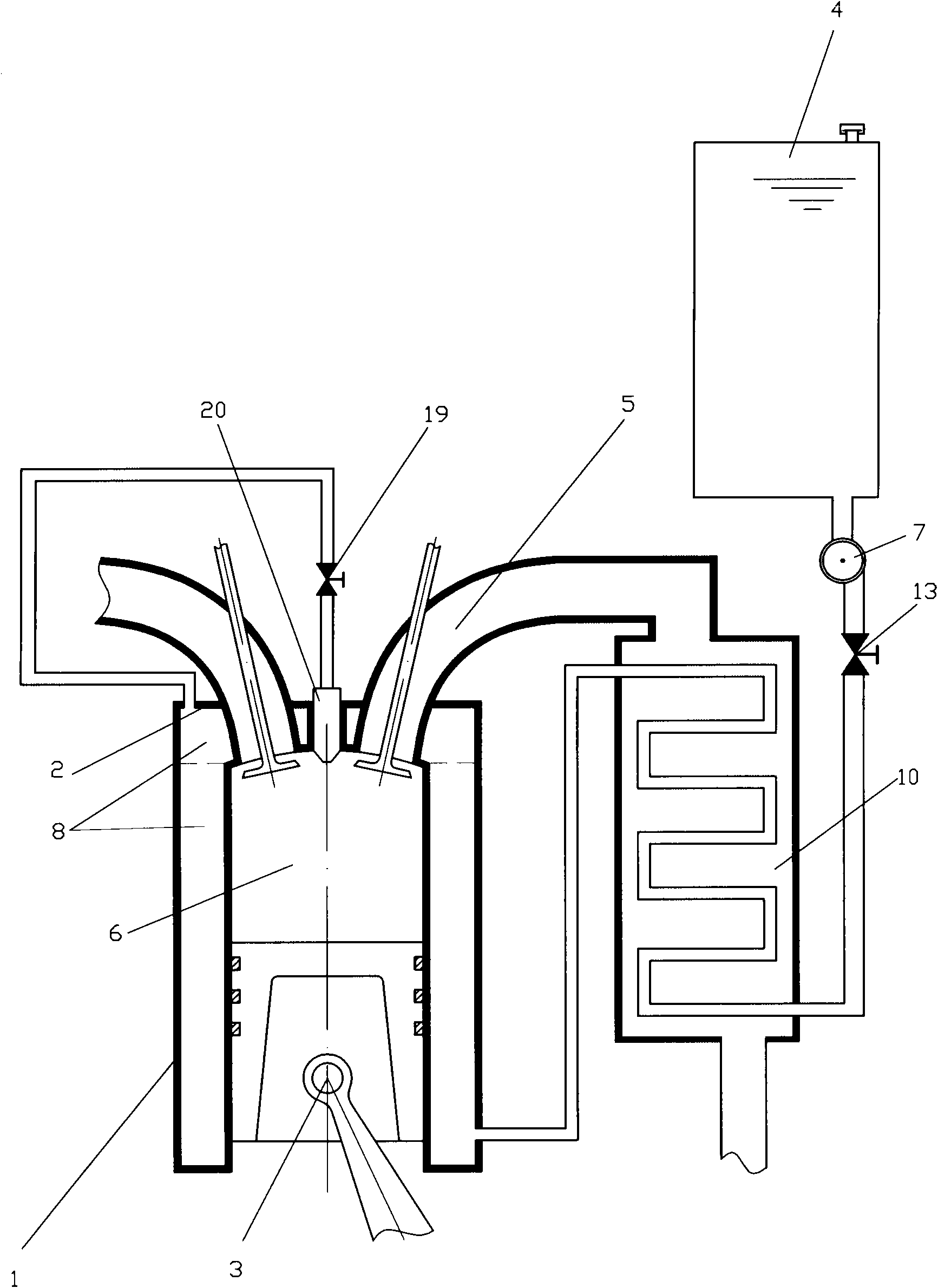
[0061] Such as figure 1The low-entropy co-combustion engine shown includes a cylinder 1, a cylinder head 2, a piston 3, a working medium storage tank 4, an exhaust passage 5 and a combustion chamber 6, and the inside of the side wall of the cylinder 1 and the inside of the cylinder head 2 are provided with high pressure The fluid channel 8, the pressure bearing capacity of the high-pressure fluid channel 8 is greater than or equal to 1MPa, the low-entropy co-combustion engine also includes an exhaust heat exchanger 10, and the exhaust channel 5 communicates with the heating fluid inlet of the exhaust heat exchanger 10; The outlet of tank 4 communicates with the heated fluid inlet of exhaust heat exchanger 10 through high-pressure pump 7, and the heated fluid outlet of exhaust heat exchanger 10 communicates with the inlet of high-pressure fluid passage 8; the outlet of high-pressure fluid passage 8 is sprayed The control valve 19 communicates with the steam injector 20, the ste...

Embodiment 2

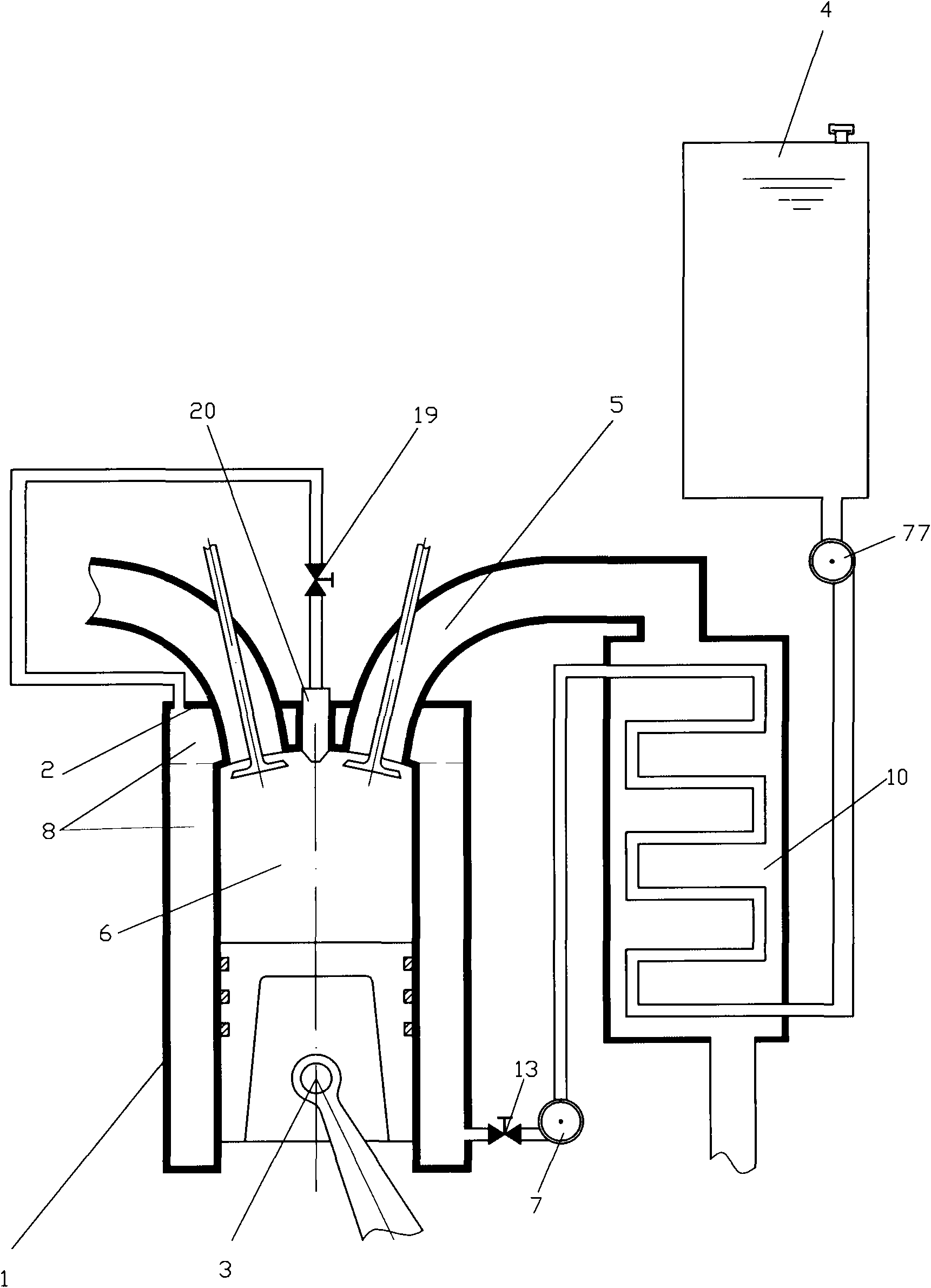
[0064] Such as figure 2 The difference between the shown low-entropy co-combustion engine and Embodiment 1 is that the outlet of the working fluid storage tank 4 communicates with the heated fluid inlet of the exhaust heat exchanger 10 through the high-pressure fluid pump 77, and the exhaust heat exchanger 10 The heated fluid outlet is communicated with the inlet of the high-pressure fluid channel 8 through the high-pressure pump 7 . The pressure-bearing capacity of the high-pressure fluid channel 8 is greater than or equal to 2MPa. A total flow control valve 13 is arranged at the outlet of the high-pressure fluid pump 77 to control the total flow of the required working fluid. When the low-entropy mixed-combustion engine is working normally, the high-pressure The cooling medium in the fluid channel 8 is in a supercritical state.

[0065] The purpose of installing the high-pressure fluid pump 77 is to ensure the circulation pressure of the vaporized cooling medium and ensure...

Embodiment 3

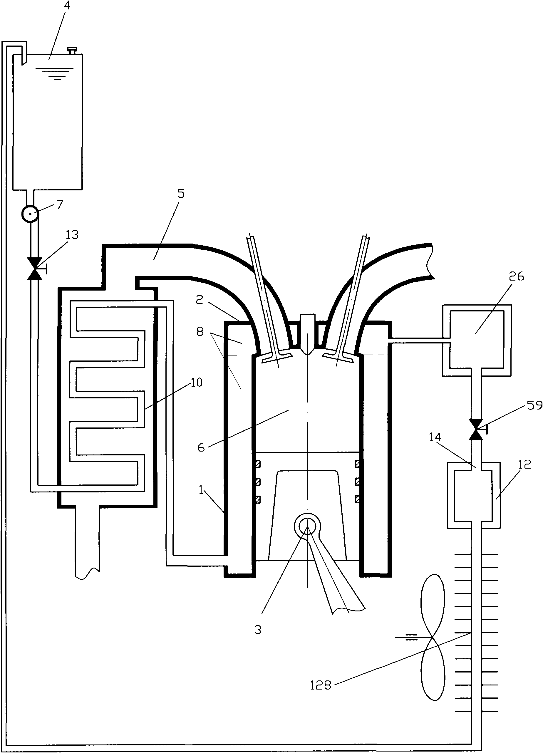
[0067] Such as image 3 The difference between the shown low-entropy co-combustion engine and Embodiment 1 is that the outlet of the high-pressure fluid passage 8 communicates with the working medium inlet 14 of the heat engine 12 through the flow control valve 59, and the high-temperature and high-pressure fluid generated in the high-pressure fluid passage 8 The working medium pushes the heat engine 12 to do work. A high-pressure working fluid storage tank 26 is installed before the flow control valve 59, which can meet the requirements of the peak power of the engine and balance the pressure of the steam system. When the engine needs a large peak power, the steam injection volume of the cylinder can be increased to increase the output power of the engine. . A closed condensing cooler 128 is arranged at the working medium outlet of the heat engine 12, and the liquid outlet of the closed condensing cooler 128 communicates with the working medium storage tank 4, so that the co...


PUM

PropertyMeasurementUnit
Pressure enduranceaaaaaaaaaa

Abstract

The invention discloses a low-entropy mixed-fuel engine which comprises an air cylinder, an air cylinder cover, a piston, a working medium storage box, an exhaust passage and a combustion chamber. A high-pressure fluid channel is arranged inside or outside of a side wall of the air cylinder and inside or outside of the air cylinder cover; the bearing capability of the high-pressure fluid channel is more than or equal to 1MPa; the low-entropy mixed-fuel engine also comprises an exhaust heat exchanger, wherein the exhaust passage is communicated with an inlet of a heating fluid of the exhaust heat exchanger; an outlet of the high-pressure fluid channel is communicated with a steam ejector through an ejection control valve; the steam ejector is communicated with the combustion chamber, and the ejection control valve is set to be a correct-time control valve; or an outlet of the high-pressure fluid channel is communicated with an inlet of a working medium of a heat engine, and the working medium of the high-temperature high-pressure fluid generated in the high-pressure fluid channel pushes the heat engine to apply work. Because the low-entropy mixed-fuel engine effectively utilizes the afterheat of the engine, the heat-power conversion efficiency of the engine is improved with energy-saving and environment protection.

Description

technical field [0001] The invention relates to the field of engines, in particular to a low-entropy co-combustion engine. technical background [0002] As we all know, the heat discharged by the traditional engine through the cooling system and the exhaust system accounts for about two-thirds of the fuel energy of the engine, and the engine cooling system and the exhaust system each account for about half, that is to say, the heat emitted by the engine cooling system accounts for about 2 / 3 of the fuel energy. one-third of. The utilization of engine waste heat has long been the focus of improving engine efficiency. However, due to the structural characteristics of traditional engines, the pressure bearing capacity of the cooling medium passages in the cooling system, especially the cylinder liners, cylinder heads and other components, is generally less than 0.3MPa. Under this pressure bearing capacity, the cooling water in the cooling medium passages It is difficult to dir...

Claims


Application Information

Patent Timeline
IPC IPC(8): F02M25/038
Inventor 靳北彪
Owner 靳北彪
Why Eureka
Try Eureka