Kiln tail waste heat boiler with independent economizer and waste heat recovery system

A waste heat boiler and economizer technology, applied in furnaces, waste heat treatment, furnace components, etc., can solve problems such as heat waste, achieve the effects of reducing water injection, improving main steam quality, and increasing power generation

Inactive Publication Date: 2010-09-15
SOUTH CHINA UNIV OF TECH
View PDF6 Cites 7 Cited by
  • Summary
  • Abstract
  • Description
  • Claims
  • Application Information

AI Technical Summary

Problems solved by technology

However, since the output of the raw meal mill is greater than the consumption of the cement kiln, the raw meal mill has to stop grinding for several hours every day. During the stoppage, the SP furnace still emits waste gas at 190-250°C. This part of the waste gas is dedusted Empty, this part of the heat is all wasted

Method used


Image

  • Kiln tail waste heat boiler with independent economizer and waste heat recovery system
  • Kiln tail waste heat boiler with independent economizer and waste heat recovery system
  • Kiln tail waste heat boiler with independent economizer and waste heat recovery system

Examples


Embodiment 1

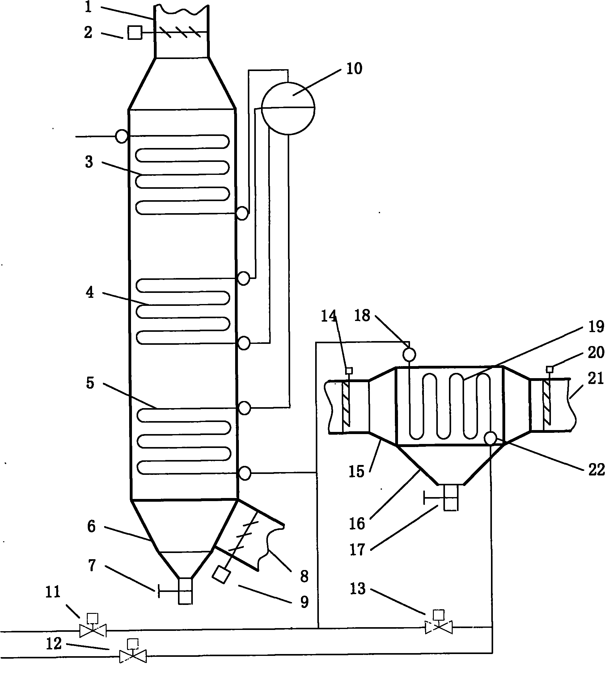
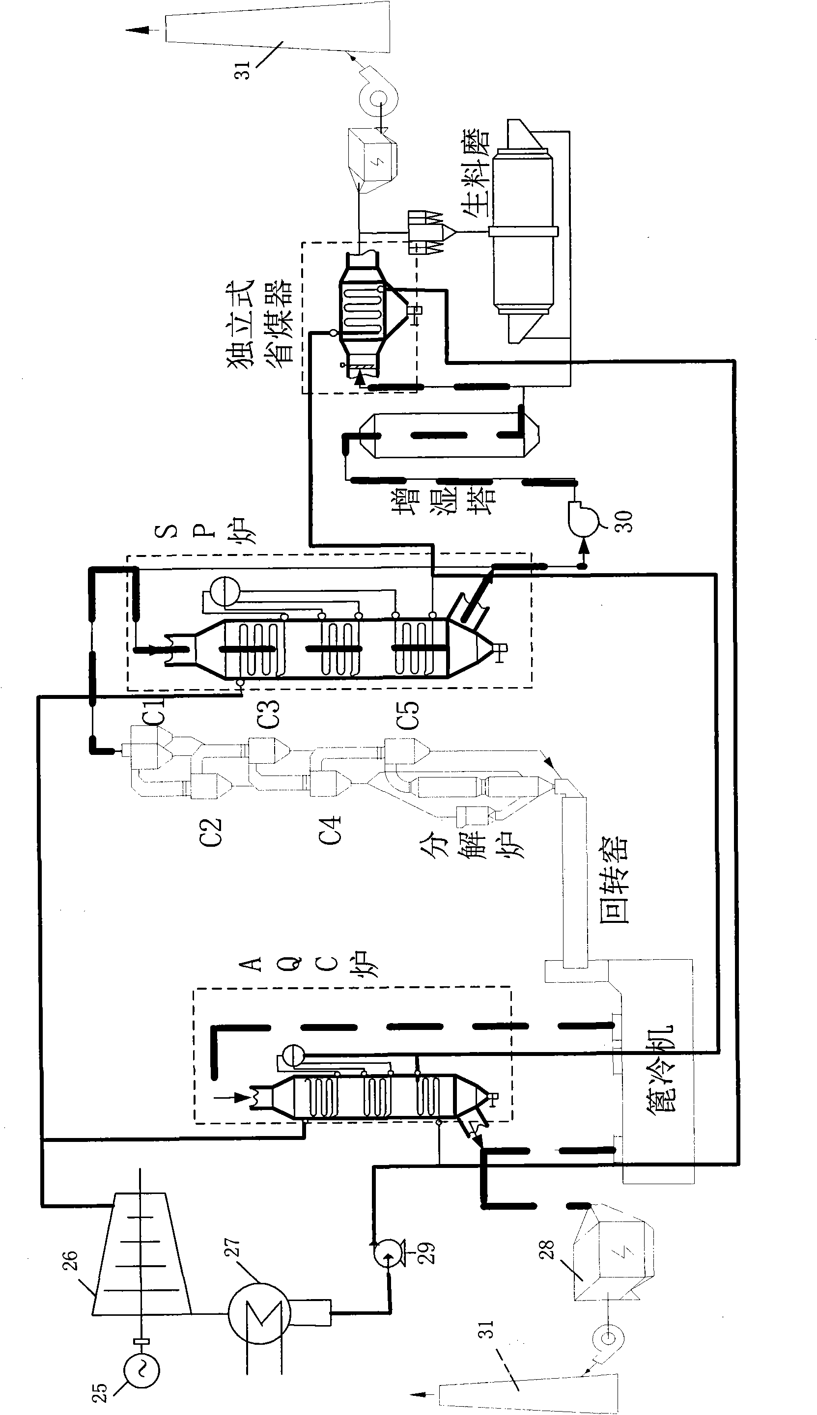
[0027] In this embodiment, a kiln tail waste heat boiler and waste heat recovery system with an independent economizer can recover waste heat to the greatest extent by designing a new kiln tail waste heat boiler and waste heat recovery process. The designed kiln waste heat boiler is as follows: figure 1 As shown, the connection method of the smoke, air, steam and water pipelines is as follows Figure 4 As shown, the specific structure is as follows:

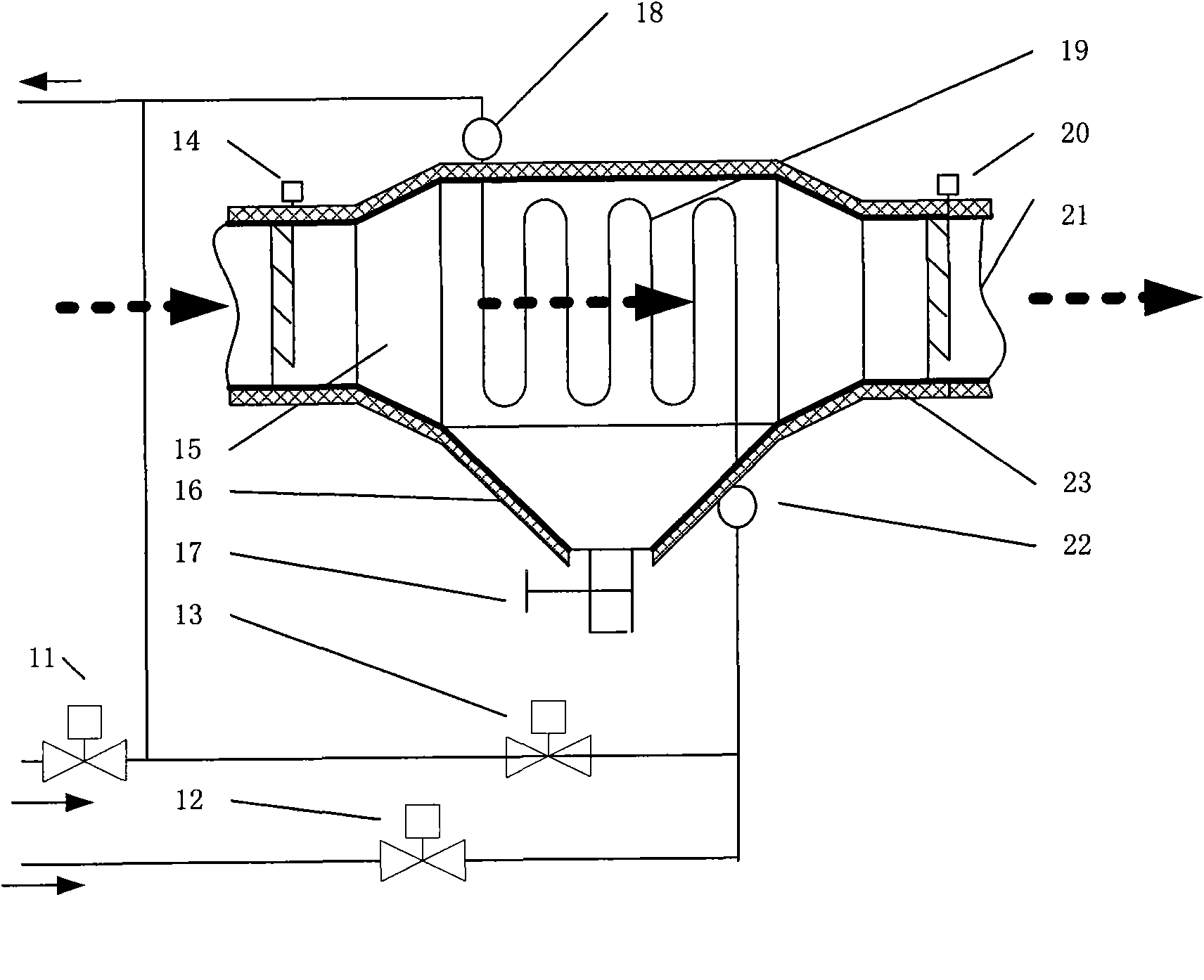
[0028] The kiln tail waste heat boiler with independent economizer consists of two parts: the kiln tail boiler body and the independent economizer. The body of the kiln tail boiler consists of flue gas inlet pipe 1 of the kiln tail boiler body, 2 inlet dampers of the kiln tail boiler body, 8 flue gas outlet pipes of the kiln tail boiler body, 9 outlet air valves of the kiln tail boiler body, and ash leakage of the kiln tail boiler body The bucket 6, the feeding valve 7 of the kiln tail boiler body, the superheater 3, the evapor...

Embodiment 2

[0035] A kiln tail waste heat boiler and waste heat recovery system with an independent economizer in this embodiment, such as Figure 5 As shown, compared with Example 1, the difference is that only superheater and evaporator are installed on the body of the waste heat boiler at the kiln tail, and the corresponding steam-water flow is: two water supply pipelines, one from the feedwater pump main pipe Pipe AD, another water supply pipe BC from the outlet of AQC furnace public economizer. The water supply pipe from the main pipe of the feed water pump is connected to the water inlet header of the independent economizer, and the water supply bypass pipe DE is set. The water supply pipes of the public economizer converge at point C, and then connected to the steam drum 10 of the waste heat boiler at the kiln tail.

[0036] Such as Figure 5 ,Such as Figure 4 , including waste heat recovery system of waste heat boiler at kiln tail with independent economizer, including waste h...

Embodiment 3

[0039] A kiln tail waste heat boiler and waste heat recovery system with an independent economizer in this embodiment, such as Image 6 As shown, compared with Example 1, the difference is that only one water supply pipe CD is provided for the waste heat boiler at the kiln tail, but the public economizer of the AQC boiler is provided with a bypass water pipe AC. The corresponding steam water flow is: the water supply pipe is divided into two roads in front of the public economizer of the AQC boiler, one is the water supply pipe AB entering the public economizer, and the other is the above-mentioned public economizer bypass water pipe AC, The branch water supply pipe BC from the public economizer outlet to the SP boiler merges at point C, and the merged water supply pipe leads to the front of the independent economizer. The water pipe before the independent economizer is further divided into two routes, one is the water supply pipe DF connected to the inlet pipe of the independ...


PUM


Abstract

The invention provides a kiln tail waste heat boiler with an independent economizer and a waste heat recovery system, wherein the kiln tail waste heat boiler comprises a waste heat boiler body and an independent economizer outside the boiler; a smoke inlet pipe of the independent economizer is connected with a by-pass duct of a raw meal mill, and a smoke outlet pipe of the independent economizer is directly connected with an electric dust collector; an inlet header of the independent economizer is connected with a feed water pump, and an outlet header of the independent economizer is connected with a water inlet pipe of a boiler steam drum of the kiln tail waste heat boiler body or of the economizer of the kiln tail waste heat boiler. In the waste heat recovery system of the kiln tail waste heat boiler containing the independent economizer, a water side of the independent economizer is provided with a by-pass, and the independent economizer can be started and stopped at any time according to the demand of waste heat recovery so as to furthest recover smoke waste heat which cannot be completely utilized when the raw meal mill is run and the smoke waste heat which cannot be utilized when the raw meal mill is stopped and is used for heating and supplying water and improving the waste heat recovery rate of the kiln tail waste heat boiler and the generated energy of the whole system.

Description

technical field [0001] The invention relates to the technical field of medium and low temperature exhaust gas waste heat boilers, in particular to a kiln tail waste heat boiler and a waste heat recovery system for recovering the waste heat of the kiln tail flue gas of a new dry process rotary kiln. Background technique [0002] Recycling and utilizing the waste heat of waste gas in the cement clinker production line to generate electricity is an important way for the cement industry to save energy and reduce consumption, and it is also a new technology. This technology uses the medium and low temperature exhaust gas discharged from the grate cooler and the waste heat of the flue gas discharged from the kiln tail preheater to heat the feed water to generate steam to drive the turbogenerator unit to generate electricity. The flue gas produced by the new dry process production line is discharged after the raw meal is preheated by the kiln tail preheater, and the temperature is ...

Claims


Application Information

Patent Timeline
IPC IPC(8): F27D17/00
CPCY02P10/25
Inventor 陆继东张向卢志民陆艳华董美蓉蔡吕清
Owner SOUTH CHINA UNIV OF TECH
Why Eureka
Try Eureka