Integrated waste heat generating and heating system and process flow thereof

A technology of waste heat power generation and process flow, which is applied in the direction of hot water central heating system, heating system, and process efficiency improvement, etc., can solve the problems of increasing the pollution coefficient, ineffective utilization, pollution, etc., and achieves a simple overall structure. , Conducive to environmental protection, the effect of reducing thermal pollution

Inactive Publication Date: 2010-10-06
童裳慧
View PDF0 Cites 25 Cited by
  • Summary
  • Abstract
  • Description
  • Claims
  • Application Information

AI Technical Summary

Problems solved by technology

The disadvantages of this technology are obvious: due to the use of supplementary combustion boilers, the whole system is more complicated, the operation is unstable and the operation cost is high, and the pollution coefficient (sulfur emission, etc.) will be increased while the production system is polluted, and coal must be wasted Carbon and other non-renewable resources
However, the pure low-temperature waste heat power generation technology without supplementary combustion generally has unsatisfactory waste heat utilization efficiency, low waste heat conversion efficiency, low power generation, and large investment
[0004] The waste heat power generation technology with supplementary combustion boiler and the pure low temperature waste heat power generation technology without supplementary combustion currently have the following three problems: ①The heat transfer tube is often blocked by ash, and the efficiency of the waste heat boiler will gradually decrease after a long time until it cannot meet the requirements. Power generation is required, and this process may happen once every three to six months at present, causing the system to be shut down for maintenance. ②The heat transfer tubes will wear out and leak if they are washed by particles for a long time, causing the system to be paralyzed, or even Affect the safety and normal operation of the production line
(For example, waste heat power generation in a cement production line may cause this problem in about half a year) ③The flue gas after waste heat power generation is generally discharged into the atmosphere at about 150°C, and the low-temperature waste heat released by the thermal power plant accounts for 30% of the entire waste heat resource. Left and right, this part of waste heat cannot be effectively utilized in the above-mentioned waste heat power generation technology with supplementary combustion boiler and pure low temperature waste heat power generation technology without supplementary combustion

Method used


Image

  • Integrated waste heat generating and heating system and process flow thereof
  • Integrated waste heat generating and heating system and process flow thereof
  • Integrated waste heat generating and heating system and process flow thereof

Examples


Embodiment Construction

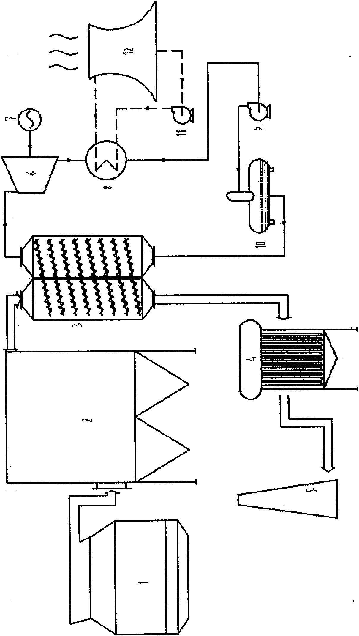
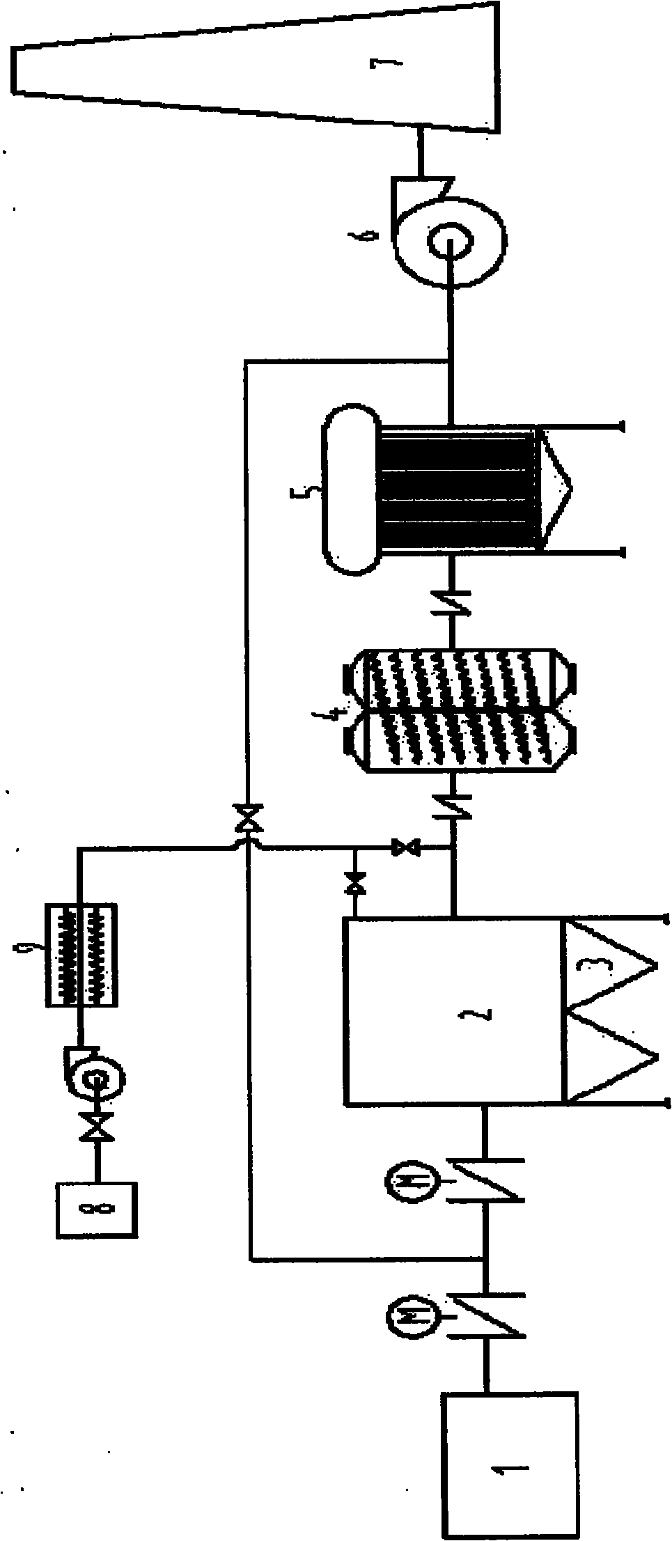
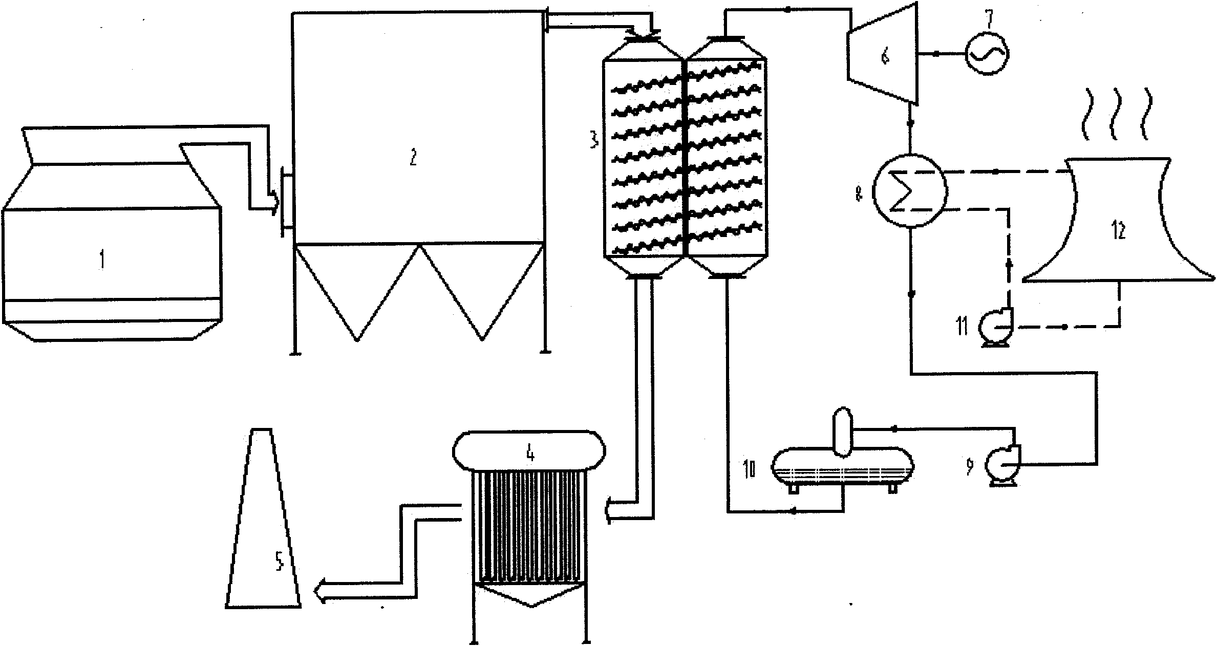
[0025] like figure 1 , 2 Shown in: waste heat power generation and heating integrated equipment system and process, with a heat pipe waste heat boiler (3) installed at the flue gas outlet to undertake all heating functions and generate medium and low pressure steam; the medium and low pressure main steam generated by the waste heat boiler is mixed Afterwards, it enters the supplementary steam condensing turbine (6) through the pipeline, and the low-pressure steam enters the steam turbine through the supplementary steam pipeline: the exhaust steam at the tail of the steam turbine enters the condenser (8), and the condensed water enters the vacuum deaeration through the condensate pump (9) and the pipeline The water after deoxygenation in the deaerator enters the boiler through the boiler feed water pump (9); the exhaust gas after heat exchange enters the waste heat heating device (4) through the pipeline, and is discharged through the chimney (5). In the inlet and outlet secti...


PUM

PropertyMeasurementUnit
dust removal efficiencyaaaaaaaaaa

Abstract

The invention discloses a waste heat generating equipment system and a waste heat generating process. The system comprises a ceramic fiber dust collector (2), a rapid heat conducting heat-pipe waste heat boiler (3), a rapid heat conducting heating device (4), a steam replenishing and condensing steam turbine (6), a condenser (8), a condensing water pump (9) and a vacuum deaerator (10), wherein ceramic fiber dust collector (2) is arranged at a waste heat outlet end; the rapid heat conducting heat-pipe waste heat boiler (3) bears a steam preparing device for power generation; the rapid heat conducting heating device (4) is arranged on the smoke inlet of a boiler; medium and high-pressure main steam generated by a rapid heat conducting heat-pipe waste heat boiler is mixed and enters the steam replenishing and condensing steam turbine (6) through a pipeline; low-pressure steam enters the steam replenishing and condensing steam turbine (6) through a steam replenishing pipeline; waste steam on the tail part of the steam turbine enters the condenser (8); condensed water enters the vacuum deaerator (10) through the condensing water pump (9) and a pipeline; water from which oxygen is removed in the deaerator enters the heat-pipe waste heat boiler (3) through a water supply pump of the boiler; and low-temperature smoke discharged from the back end of the boiler is delivered into the rapid heat conducting heating device (4). The waste heat utilization ratio of the integrated system is enhanced by over 60 percent on average, so unit energy consumption of an enterprise is greatly lowered, the problem of unstable running of the system due to dust blocking of the boiler and wearing of a heat exchange tube in a medium and low temperature waste heat generating system is solved and comprehensive generating efficiency is enhanced by over 30 percent.

Description

Technical field: [0001] The invention relates to the technical field of medium and low temperature waste heat power generation and high temperature dust removal materials, and is suitable for utilizing the waste heat of medium and low temperature flue gas generated in the production process of metallurgy, cement, building materials, chemical and ceramic industries, and is especially suitable for the integrated equipment system of waste heat power generation and heating and process flow. technical background: [0002] Cement, metallurgy, building materials, chemicals, ceramics and other industrial enterprises discharge waste heat resources such as medium and low temperature flue gas, steam, and hot water at a temperature of about 250-650°C throughout the day. This part of the resources discharged in vain belongs to medium and low temperature waste heat. If recycled, the huge energy produced each year is equivalent to rediscovering a world-class large coal mine. [0003] At ...

Claims


Application Information

Patent Timeline
Patent Type & Authority Applications(China)
IPC IPC(8): F27D17/00F22B1/18F22D11/06F24D3/02F28D15/02F22B37/54F22D1/00F01L11/02B01D46/30B01D39/06
CPCY02P10/25Y02P80/15
Inventor 童裳慧
Owner 童裳慧
Why Eureka
Try Eureka