Miniature microphone manufacturing method based on Si-Si bonding process

A microphone and silicon-silicon bond technology, which is applied in the field of micro-microphone preparation based on the silicon-silicon bonding process, can solve the problems of extremely high process control requirements, poor repeatability, and increased process complexity, and achieve simple process implementation, Meet the effect of small size and avoid adhesion

Active Publication Date: 2010-10-06
无锡芯感智半导体有限公司
View PDF4 Cites 14 Cited by
  • Summary
  • Abstract
  • Description
  • Claims
  • Application Information

AI Technical Summary

Problems solved by technology

[0005] At present, there are usually two ways to improve the residual stress of the diaphragm. One is to use an additional process and annealing. This method requires extremely high process control and the repeatability is not very good; the other is through structural adjustment, such as manufacturing Free film or textured film structure, but the fabrication of this structure will increase the complexity of the process, and it may be necessary to add a multi-step process to control the diaphragm
Realizing a rigid back electrode is also a major difficulty in the microphone manufacturing process. At present, there are two main methods to solve it. One is to make a thick back electrode, but it is difficult to obtain the required thick back electrode through conventional deposition processes; One method is to improve the rigidity of the back plate through structural adjustment, but it also increases the complexity of the process

Method used


Image

  • Miniature microphone manufacturing method based on Si-Si bonding process
  • Miniature microphone manufacturing method based on Si-Si bonding process
  • Miniature microphone manufacturing method based on Si-Si bonding process

Examples


Embodiment Construction

[0030] The present invention will be further described below in conjunction with specific drawings and embodiments.

[0031] The preparation method of the miniature microphone of the present invention mainly utilizes a silicon-silicon bonding process to form a capacitive miniature microphone.

[0032] The micro-microphone preparation method based on the silicon-silicon bonding process comprises the following steps:

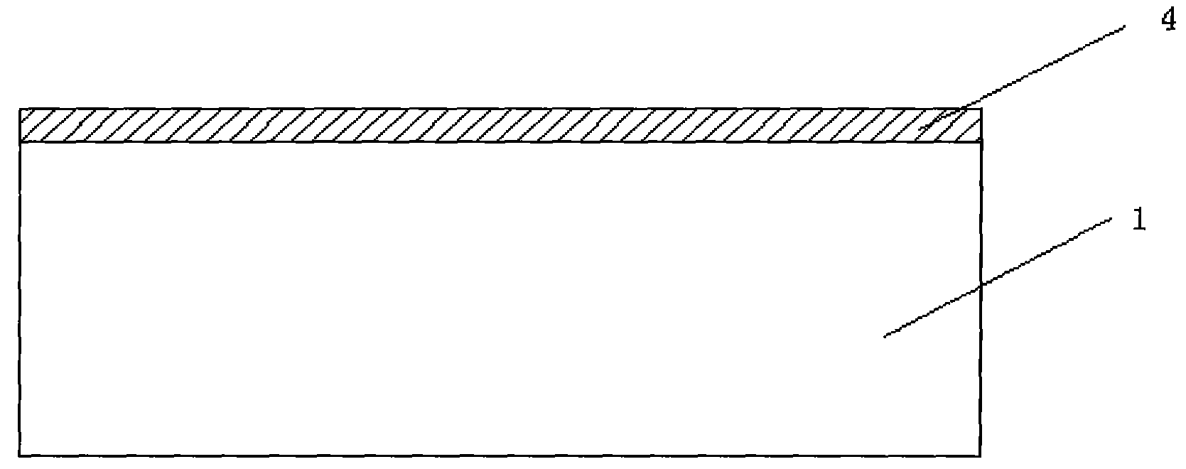
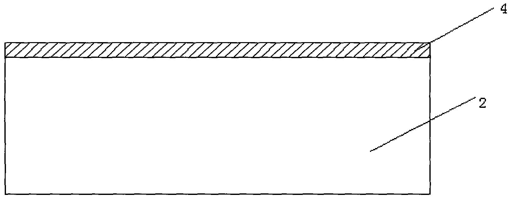
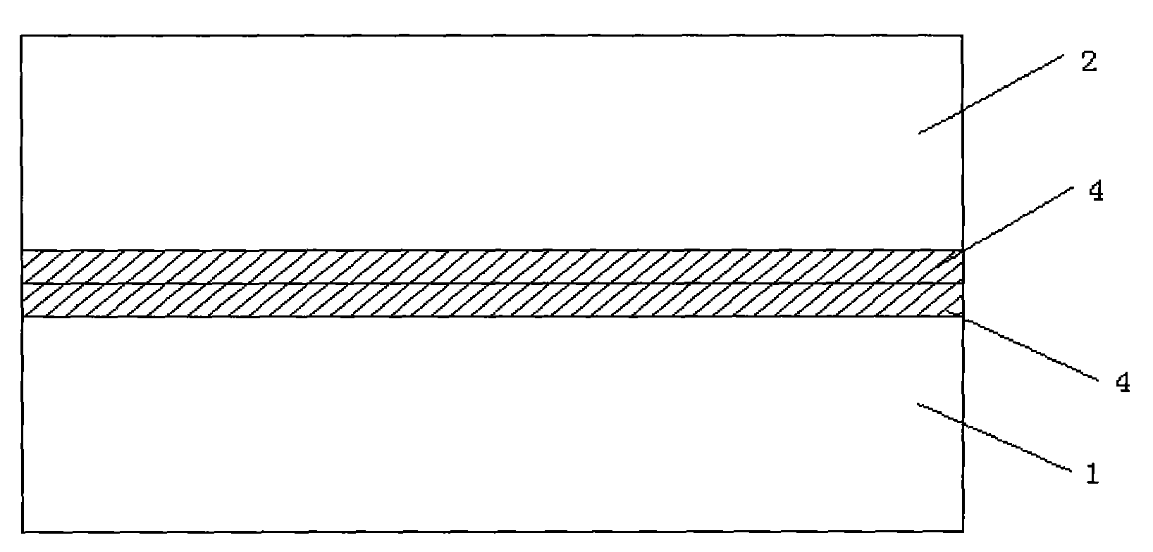
[0033] a. A connection plate 1 and a back plate 2 are provided, and an oxide layer 4 is grown on the connection plate 1 and the back plate 2; the connection plate 1 is monocrystalline silicon, and the material of the back plate 2 is doped Single crystal silicon; the oxide layer 4 is silicon dioxide, and the connection plate 1 and the back plate 2 are bonded and fixed by the corresponding oxide layer 4; the connection plate 1 is mainly used for the reliability of the thinning process of the back plate 2; The structures of plate 1 and back plate 2 are as follows: ...


PUM


Abstract

The invention relates to a miniature microphone manufacturing method based on an Si-Si bonding process, which comprises the following steps that: a. a connecting plate and a back plate are provided; b. the back plate and the connecting plate are bonded and fixed; c. the back plate is thinned; d. an insulating bonding layer is grown on the thinned back plate; e. a substrate is provided; f. an insulating supporting layer is grown on the substrate; g. a vibrating diaphragm is precipitated on the substrate; h. the vibrating diaphragm which is arranged in a groove is obtained; i. the back plate and the substrate are bonded and fixed; j. the connecting plate and an oxidization layer above the substrate are etched; k. a lower electrode hole is obtained on the back plate; l. an electrode layer isprecipitated on the back plate; m. electrodes on the back plate and the vibrating diaphragm are obtained; n. a plurality of sound holes on the back plate are obtained; and o. the other end of the substrate which corresponds to the back plate is etched to obtain a vocal cavity below the vibrating diaphragm. The miniature microphone manufacturing method based on the Si-Si bonding process has the advantages of high sensitivity, low cost, wide frequency band, high finished product rate and simple manufacturing process.

Description

technical field [0001] The invention relates to a method for preparing a miniature microphone, in particular to a method for preparing a miniature microphone based on a silicon-silicon bonding process. Background technique [0002] MEMS (Micro-Electro-Mechanical Systems) technology is a high-tech that has developed rapidly in the past few years. Compared with traditional counterparts, MEMS devices have obvious advantages in terms of volume, power consumption, and weight. The advanced semiconductor manufacturing process can realize the batch manufacturing of MEMS devices, can control the production cost extremely well, and improve the consistency of the devices. For the current MEMS products, accelerometers, pressure sensors, gyroscopes, micromirrors, silicon microphones, etc. have all been mass-produced and have occupied a certain share in the corresponding market. [0003] Silicon microphones are characterized by high temperature resistance, low power consumption, and smal...

Claims


Application Information

Patent Timeline
Patent Type & Authority Applications(China)
IPC IPC(8): H04R31/00
Inventor 刘同庆沈绍群
Owner 无锡芯感智半导体有限公司
Why Eureka
Try Eureka