
Direct current/ direct current converter and direct current/ direct current converting method

A DC converter and comparator technology, applied in the direction of conversion equipment without intermediate conversion to AC, can solve the problems of limited bandwidth of voltage adder XADD, complex ISENSE module, distortion of current detection signal, etc., to overcome efficiency and detection accuracy Contradictions, reduced structural complexity, and the effect of avoiding bandwidth limitations

Active Publication Date: 2010-10-13
PEKING UNIV
View PDF5 Cites 12 Cited by
  • Summary
  • Abstract
  • Description
  • Claims
  • Application Information

AI Technical Summary

Problems solved by technology

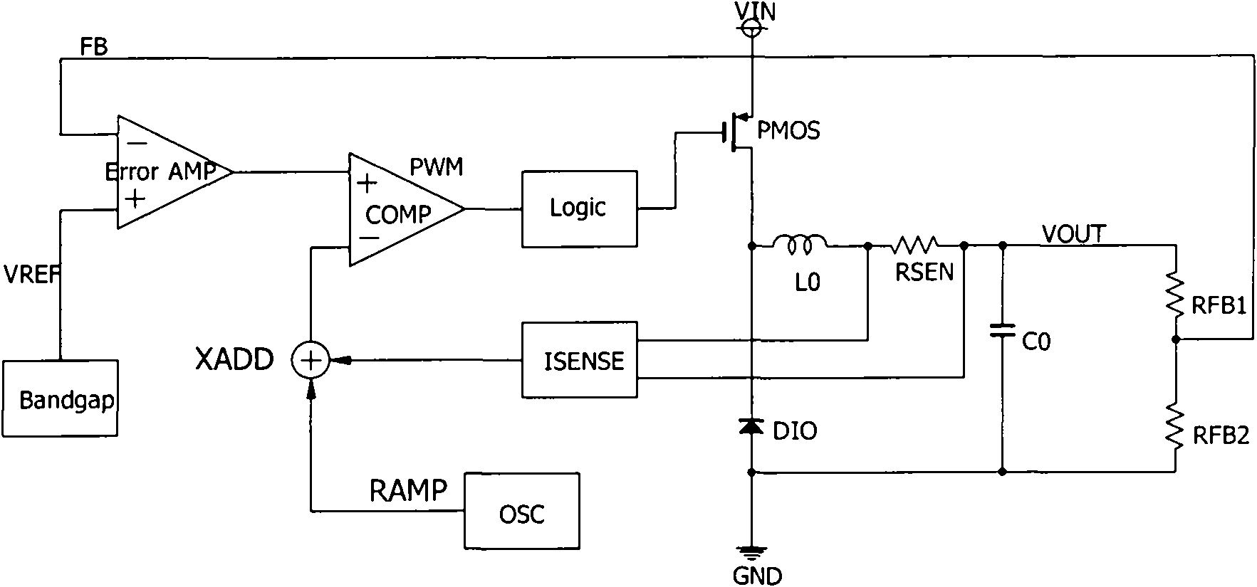
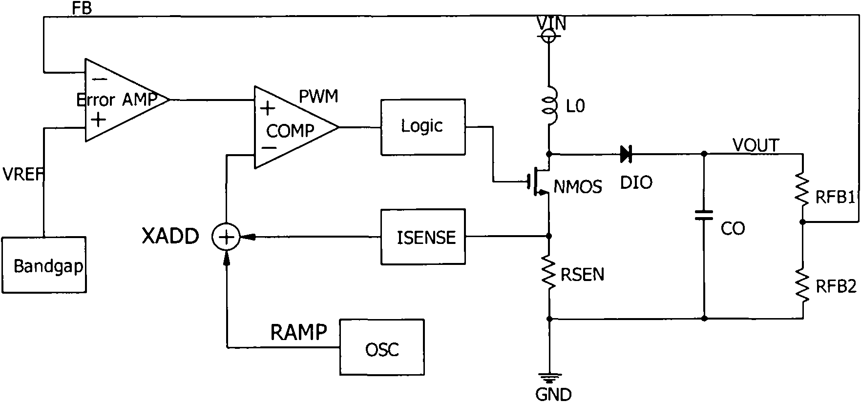
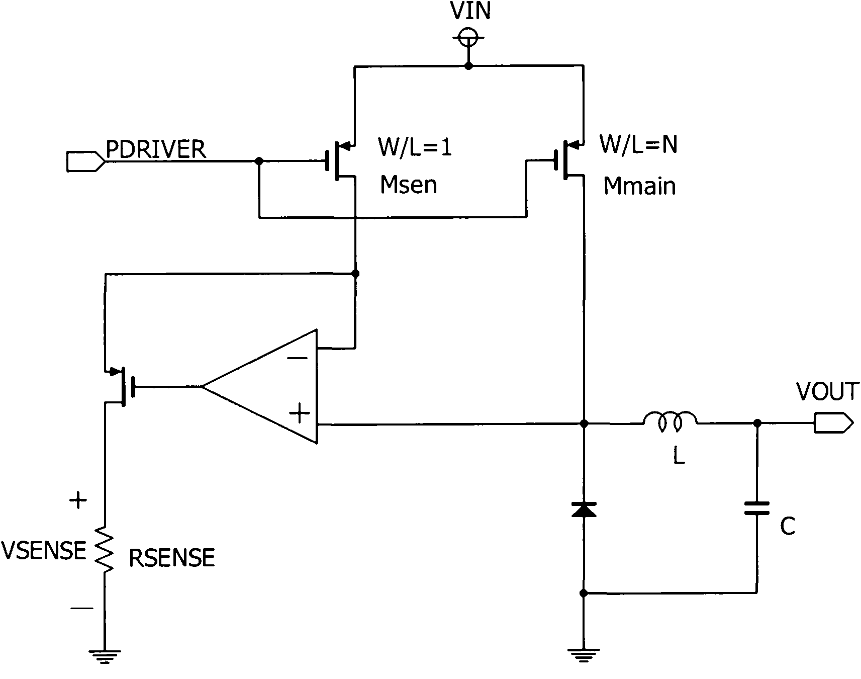
This structure is a power lossy detection method. If the power nondestructive detection structure is used, the ISENSE module will be more complicated, such as image 3 , Figure 4 The diagrams shown are a schematic diagram of a power lossless current detection circuit. To achieve high precision and high speed, the amplifier must have a high GBW (Gain Bandwidth Product). If the amplifier does not meet the requirements, there will be a large big distortion
Because ISENSE detects the voltage of the output node, converts the voltage into a current and then converts it into a voltage VSENSE, which will also cause distortion of the current detection signal.
In addition, due to the limited bandwidth of the voltage adder XADD, there will be distortion in the case of high-speed switching, which cannot meet the needs of high-frequency switching
At the same time, the current detection module ISENSE and the voltage adder XADD occupy a large chip area and increase power consumption due to their high complexity.

Method used


Image

  • Direct current/ direct current converter and direct current/ direct current converting method
  • Direct current/ direct current converter and direct current/ direct current converting method
  • Direct current/ direct current converter and direct current/ direct current converting method

Examples


Embodiment 1

[0091] This embodiment firstly describes the main frame structure of a DC / DC converter provided by the technical solution of the present invention and the corresponding DC / DC conversion method.

[0092] Such as Figure 5 As shown, the converter includes a power switch PMOS, an inductor L 0 , voltage divider circuit and bandgap reference source Bandgap;

[0093] Among them, the voltage divider circuit is mainly composed of resistors RFB1 and RFB2, and the voltage divider is obtained with V OUT proportional to the feedback voltage V FB ;

[0094] Additionally, the converter includes:

[0095] The current detection module ISENSE is respectively connected to the power switch PMOS and the inductor L 0 , for generating a current detection signal reflecting the magnitude of the current flowing through the power switch PMOS;

[0096] The oscillator OSC is connected to the current detection module ISENSE, and is used to superimpose and compensate the current detection signal to g...

Embodiment 2

[0108] This embodiment takes a step-down DC / DC converter as an example to describe the specific structure and corresponding working process of the current detection module ISENSE and the oscillator OSC contained in the converter.

[0109] Such as Image 6 As shown, the current detection module ISENSE includes an amplification unit A, a feedback capacitor C 1 , input capacitance C 2 and the first S 1 , the second S 2 , the third S 3 switch;

[0110] The first switch S 1 used to control whether the feedback capacitor is connected to the circuit;

[0111] The second switch S 2 Used to control whether the source of the power switch is connected to the circuit;

[0112] The third switch S 3 used to control whether the current detection module is connected to the drain of the power switch;

[0113] The amplifying unit A is used to amplify the difference between the power switch drain voltage and the source voltage, and then generate a current detection signal for reflectin...

Embodiment 3

[0147]This embodiment takes a step-up DC / DC converter as an example to describe the specific structure and corresponding working process of the current detection module ISENSE and the oscillator OSC included in the converter.

[0148] Such as Figure 8 As shown, the current detection module ISENSE includes an amplification unit A, a feedback capacitor C 1 , input capacitance C 2 and the first S 1 , the second S 2 , the third S 3 switch;

[0149] The first switch S 1 used to control whether the feedback capacitor is connected to the circuit;

[0150] The second switch S 2 Used to control whether the source of the power switch is connected to the circuit;

[0151] The third switch S 3 used to control whether the current detection module is connected to the drain of the power switch;

[0152] The amplifying unit A is used to amplify the difference between the power switch drain voltage and the source voltage, and then generate a current detection signal for reflecting t...


PUM


Abstract

The invention relates to a direct current / direct current converter and a direct current / direct current converting method, which belong to the technical field of microelectronics and power management. The direct / direct current converter provided by the invention reduces hardware expenditure and power consumption on the premise of meeting the requirements of a high frequency (HF) switch. The direct current / direct current converter comprises a current detecting module, an oscillator, an error amplifier, a comparator and a logic circuit, wherein the current detecting module is used for generating a current detecting signal; the oscillator is used for performing superposition compensation on the current detecting signal; the error amplifier is used for comparing feedback voltage with band gap reference voltage to obtain an error amplifying signal; the comparator is used for comparing the compensated current detecting signal with the error amplifying signal to generate a pulse width modulation signal; and the logic circuit is used for generating a control signal for controlling a power switch. Compared with traditional structure, the direct current / direct current converter has the advantages of reducing complexity, reducing function consumption, improving performance, reducing cost due to smaller chip area, and improving product competitiveness of a direct current / direct current conversion chip.

Description

technical field [0001] The invention belongs to the technical field of microelectronics and power supply management, and in particular relates to a DC / DC converter and a DC / DC conversion method. Background technique [0002] DC / DC converters have important applications in low-power circuits, portable devices, and consumer electronics products, and have the advantages of low cost, light weight, simple structure, and high reliability. DC / DC converters based on inductive energy storage are divided into step-up DC / DC converters, step-down DC / DC converters, and step-up-buck DC / DC converters. The DC / DC converter includes a power switch, and the output voltage is controlled by controlling the on-off of the power switch. [0003] There are many ways of traditional current feedback, generally focusing on the method of first detecting the current and then generating the control voltage. According to the different methods of current detection, it can be divided into several types: usi...

Claims


Application Information

Patent Timeline
Patent Type & Authority Applications(China)
IPC IPC(8): H02M3/07
Inventor 赵汗青鲁文高陈中建方然王新安聂辉鞠原吉利久
Owner PEKING UNIV
Learn More