Whirlpool separator

A vortex separation and vortex chamber technology, applied in the field of vortex separators, can solve the problems of unavailability of resources, general mineral processing effect, high cost of seawater desalination, and solve the problem of greenhouse gas emission, water pollution, and water shortage. Effect

Inactive Publication Date: 2010-11-03
陈久斌
View PDF0 Cites 9 Cited by
  • Summary
  • Abstract
  • Description
  • Claims
  • Application Information

AI Technical Summary

Problems solved by technology

[0002] Existing separation equipment mainly includes centrifuges, separators, etc., which generally have defects such as high equipment cost, average separation effect, and high energy consumption.
The existing sewage treatment equipment is complicated, the cost is too high, the cost of sewage treatment is too high, and the treatment effect is average
The existing seawater desalination equipment is complicated, the cost is too high, the cost of seawater desalination is too high, and the energy consumption is too large
Existing marine chemical equipment is complicated and expensive, and the effect on the utilization of marine resources is not ideal
The existing air purification equipment has a general purification effect and cannot thoroughly treat dust, carbon dioxide, nitrogen oxides, and sulfur oxides
Existing vacuuming equipment has unsatisfactory vacuuming effect, high noise, and dust particles pollute the air, and it is troublesome to deal with dust after dust removal
Existing dust removal equipment includes cyclone dust removal, electric dust removal, bag dust removal, etc., which generally have defects such as unsatisfactory dust removal effect and high energy consumption.
The cost of existing mineral processing equipment is too high, the mineral processing effect is average, and finer separation cannot be achieved,

Method used


Image

  • Whirlpool separator
  • Whirlpool separator
  • Whirlpool separator

Examples


Embodiment Construction

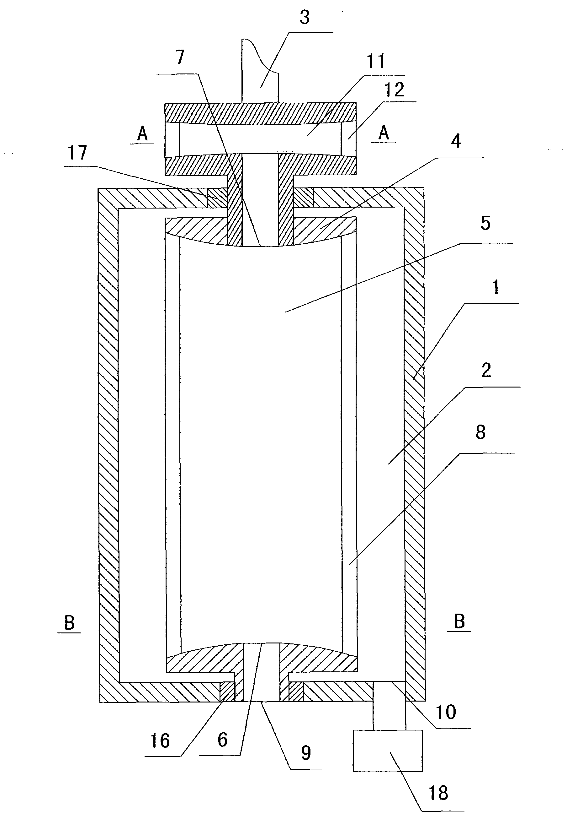
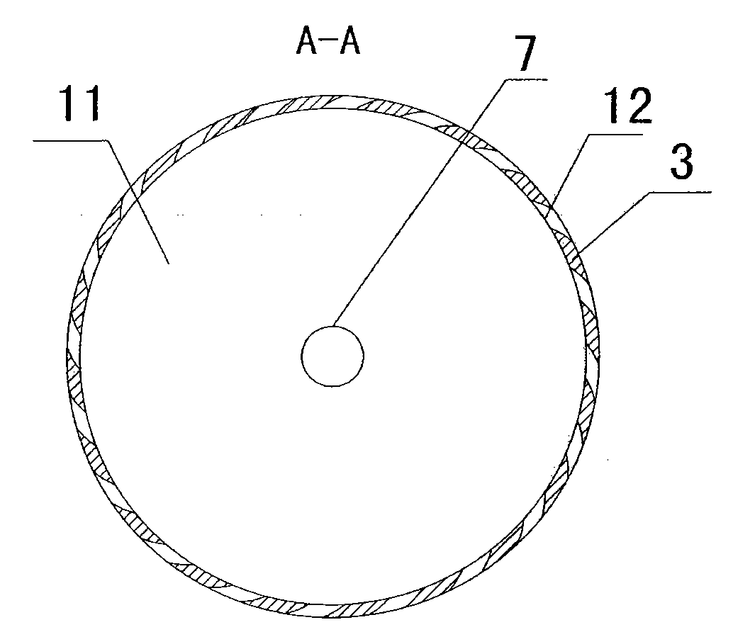
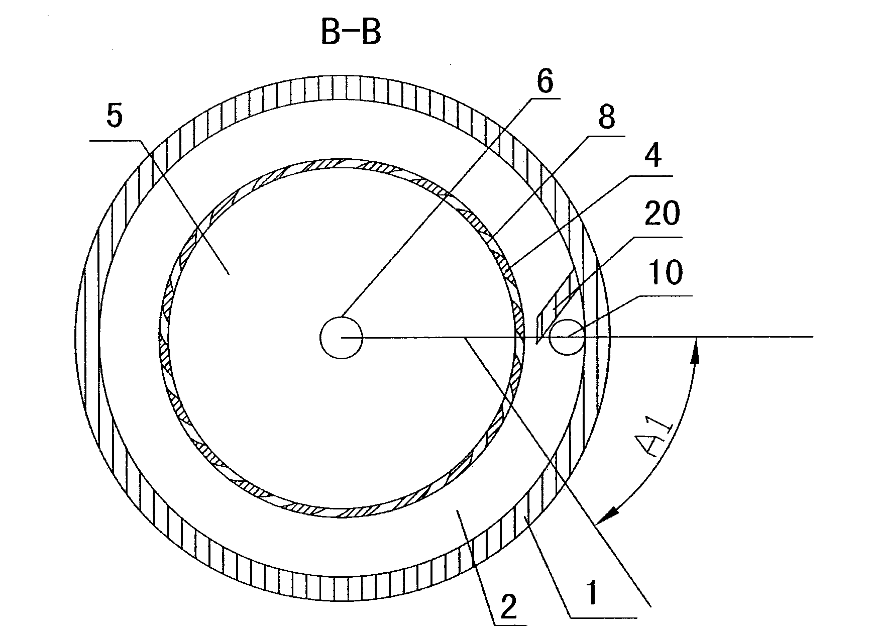
[0035] The main structure of the eddy current separator of the present invention includes a housing 1, at least one housing chamber 2 is arranged in the housing 1, a transmission device 3 is installed in the housing 1, a vortex separation cylinder 4 is arranged in the housing chamber 2, the transmission device 3 and the eddy current separation cylinder 4 connection, a vortex separation chamber 5 is provided in the vortex separation cylinder 4, a fluid inlet 6 is provided at one end of the vortex separation chamber 5, a fluid outlet 7 is provided at the other end of the vortex separation chamber 5, and a vortex separation chamber outlet 8 is provided on the outer periphery of the vortex separation chamber 5, and the housing cavity 2 A housing cavity inlet 9 is provided, and the housing cavity 2 is provided with at least one housing cavity outlet 10 .

[0036] The scope of the casing 1 includes a base, a casing, and a power unit, and each part can be collectively referred to as a...


PUM


Abstract

A whirlpool separator is composed of a casing and a drive shaft, wherein the casing is internally provided with a casing cavity and the drive shaft; the casing cavity is internally provided with a whirlpool wheel connected with the drive shaft; the whirlpool wheel is internally provided with a whirlpool chamber the middle of which is provided with a whirlpool chamber inlet, and the periphery of the whirlpool chamber is provided with a whirlpool chamber outlet; and the casing cavity is provided with a casing cavity inlet arranged corresponding to the whirlpool chamber inlet, and the casing cavity is provided with a casing cavity outlet. The whirlpool separator in the invention adopts a brand new separation principle and a method, makes full use of circular motion and fluid motion, and utilizes a whirlpool the rotation speed of which increases from the periphery to the center progressively to separate the fluid therein. The invention can be widely applicable to the fields of sewage treatment, refuse treatment, oredressing, sea water desalination, ocean chemical industry, hydrogen production, oxygen production, nano material manufacture, carbon dioxide decomposition, harmful gas decomposition, air conditioning, refrigeration, reactor, oil refining, air purification, dust abatement, dust absorption and the like, can provide inexhaustible clean energy, can thoroughly solve the energy problem and leads to industrial revolution in various industries.

Description

technical field [0001] The present invention relates to separator equipment, centrifuge equipment, sewage treatment equipment, seawater desalination equipment, marine chemical equipment, mineral processing equipment, garbage treatment equipment, hydrogen production equipment, carbon dioxide decomposition treatment equipment, harmful gas decomposition treatment equipment, nano material manufacturing equipment, Reactor equipment, air purification equipment, dust removal equipment, vacuum equipment, air conditioning, refrigeration equipment, oxygen production equipment and other fields, specifically a vortex separator. Background technique [0002] Existing separation equipment mainly includes centrifuges, separators, etc., which generally have defects such as high equipment cost, mediocre separation effect, and high energy consumption. The existing sewage treatment equipment is complicated, the cost is too high, the sewage treatment cost is too high, and the treatment effect i...

Claims


Application Information

Patent Timeline
IPC IPC(8): B04B5/12
Inventor 陈久斌
Owner 陈久斌
Why Eureka
Try Eureka