Nanocrystalline wood floor geothermal composite structure

A nano-microcrystalline and composite structure technology, applied in heating methods, electric heating systems, household heating, etc., can solve problems such as waste of water resources, complicated installation work, waste of resources, etc., to enhance dimensional stability, alleviate peak-valley electricity consumption, etc. Contradictions, the effect of strengthening the heat storage capacity

Inactive Publication Date: 2010-11-10
吉林爱尔得板材科技有限公司
View PDF6 Cites 21 Cited by
  • Summary
  • Abstract
  • Description
  • Claims
  • Application Information

AI Technical Summary

Problems solved by technology

[0003] ① Huge waste of resources; traditional heating takes up valuable land resources to build boiler rooms, coal storage yards, and slag discharge yards. Since water is used as the heat transfer medium, a large amount of increasingly scarce water resources are wasted; the heating pipeline route is long, Running, popping, dripping, and leaking are inevitable, which will cause waste of hot water
[0004] ② Serious pollution; using traditional heating, coal and slag will cause environmental pollution during transportation and storage; in addition, necessary equipment in the boiler operation process such as: coal loading machine, grate machine, slag remover, induced draft fan, blower, circulation Pumps, etc., will emit noise during operation and will also pollute the environment; in addition, lubricating oil during mechanical operation and cleaning agents used during maintenance will cause ground and drainage pollution
[0005] ③Passive heating: The traditional heating method is passive heating. As long as the heating fee for the whole winter is paid, how to use it is up to the user. Cause energy waste; In addition, if the heating period is not reached or the heating period has passed, even if you feel cold,

Method used


Image

  • Nanocrystalline wood floor geothermal composite structure
  • Nanocrystalline wood floor geothermal composite structure

Examples


example 1

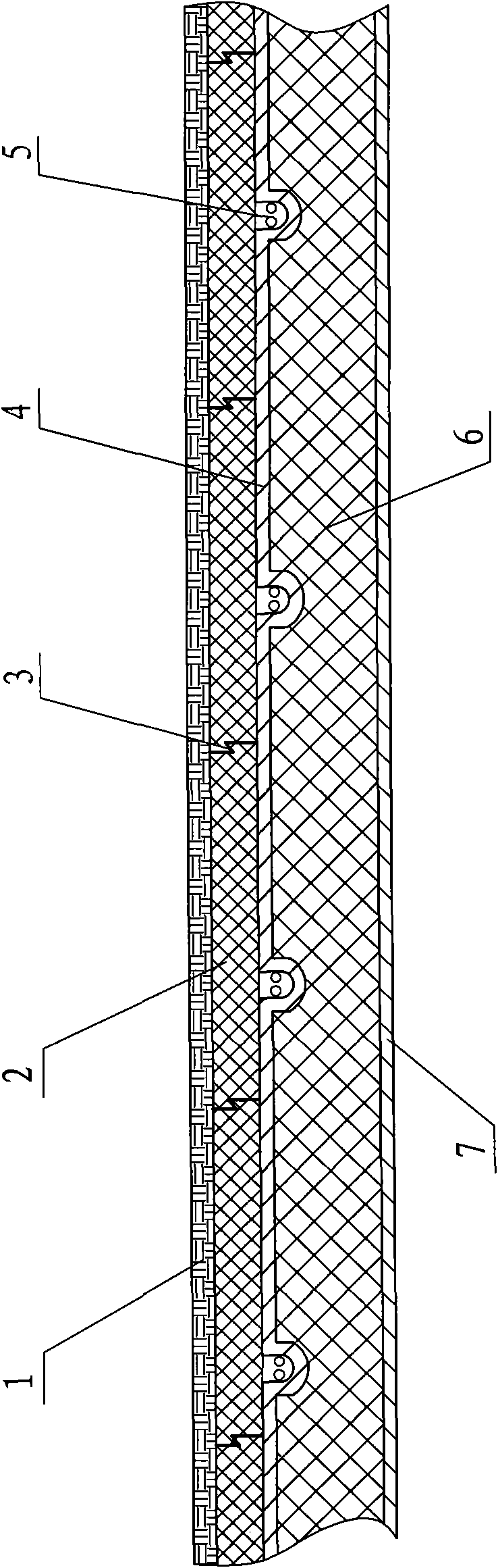
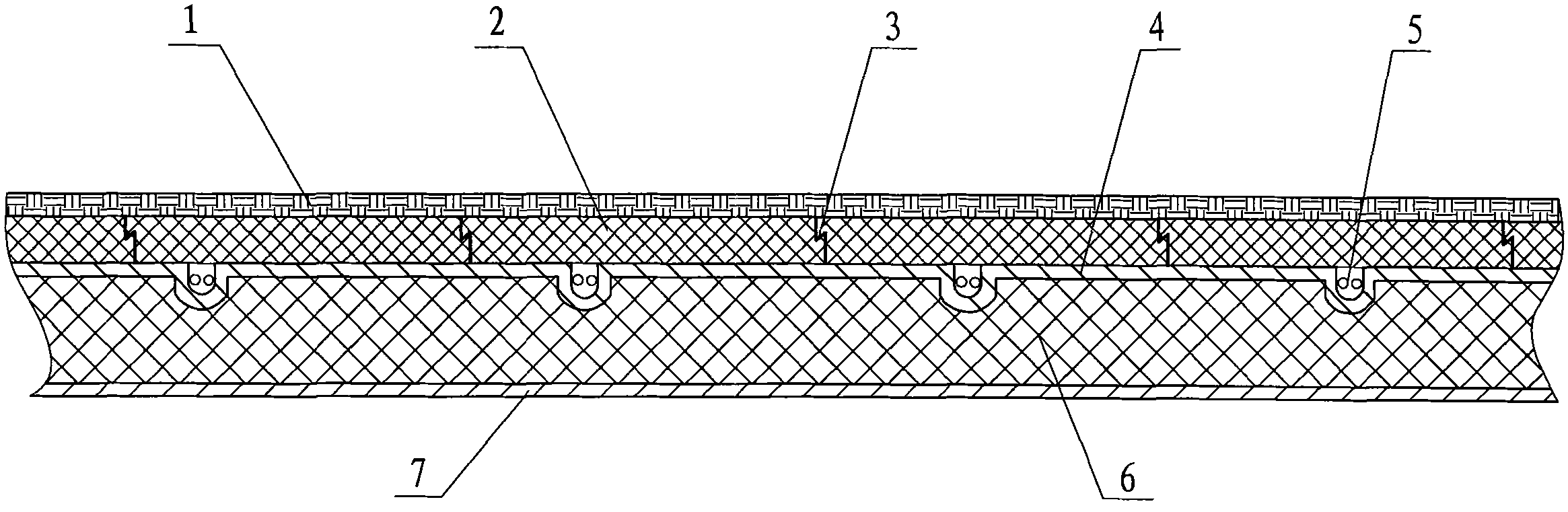
[0027] Depend on figure 1 As shown, 2 in the figure is the nano-microcrystalline wood floor layer, 6 is the XPS extruded board heat insulation layer, and a closed groove is evenly opened on the upper part of the XPS extruded board heat insulation layer 6, and the XPS extruded board heat insulation layer is evenly opened. The upper part of the heat layer 6 and the closed groove part are evenly distributed with an aluminum heat-conducting layer 4, and the bending part of the closed groove is an arc-shaped groove; the closed groove with the aluminum heat-conducting layer 4 is covered with silica gel Heating cable 5, the silicone heating cable 5 is connected to the power supply through a temperature control switch with a temperature sensor; a nano-microcrystalline wood floor layer 2 with a wear-resistant surface layer 1 is directly laid on the top of the heat conduction layer. In addition, a metal heat reflection layer 7 is directly laid on the lower part of the XPS extruded board...


PUM


Abstract

The invention discloses a nanocrystalline wood floor geothermal composite structure, comprising an extruded sheet thermal-protective coating and a heat conduction floor layer. The technical key points are as follows: the upper part of the extruded sheet thermal-protective coating is evenly provided with closed grooves, the upper part of the extruded sheet thermal-protective coating and the closed groove positions are respectively distributed with a heat conduction layer evenly, a heating cable is paved in the closed groove with the heat conduction layer, and the upper part of the heat conduction layer is directly paved with the heat conduction floor layer with a wear-resistant surface course. The composite structure is not manufactured by lyophobic materials, thus having waterproof function. When in use, a user can set the temperature by proper motion as required, and especially at night, night off-peak electricity is introduced for warming, thus alleviating the peak electricity conflicts of a grid transmission system, replacing a coal-fired boiler and satisfying large area heating. The invention also has the characteristics of simple and reasonable structure, environment protection without pollution, small occupied area, low heating cost, long service life, wide application range, capability of being widely used indoor and outdoor and the like.

Description

technical field [0001] The invention relates to the technical field of thermal conduction floor for civil use, in particular to a geothermal composite structure of nano-microcrystalline wood floor. Background technique [0002] With the continuous development of society and the continuous progress of science and technology, people's living standards and quality requirements are also constantly improving. As we all know, in recent years, the winter heating method has gradually changed from the traditional casting radiator heating method to a diversified heating method. For example: the "geothermal" heating method of aluminum-plastic pipes, the air-conditioning hot air heating method, the electric heating method, and stainless steel or aluminum alloy heaters, among which the "geothermal" heating method of aluminum-plastic pipes is the most popular. The above-mentioned "geothermal" heating method has indeed relatively beautified the indoor environment and relatively improved t...

Claims


Application Information

Patent Timeline
IPC IPC(8): F24D13/00F24D3/14E04F15/02
CPCY02B30/00
Inventor 钟锋
Owner 吉林爱尔得板材科技有限公司
Why Eureka
Try Eureka