Anaerobic baffle plate type microbial fuel cell stack

A technology of fuel cell stacks and microorganisms, applied in the direction of biochemical fuel cells, fuel cells, fuel cells, etc., can solve the problems of reduced power generation performance, complex battery stack system, and low output performance, and achieve strong shock load resistance and easy The effect of expanding the amplification and improving the removal efficiency

Inactive Publication Date: 2010-12-08
PEKING UNIV
View PDF1 Cites 16 Cited by
  • Summary
  • Abstract
  • Description
  • Claims
  • Application Information

AI Technical Summary

Problems solved by technology

[0004] First, the output performance is low. The slow electron transfer rate of the biological system is the main factor limiting the power generation of MFC. The theoretical open circuit voltage is only 1.14V, which is affected by factors such as activation loss, ohmic loss and concentration polarization in the circuit. The actual output voltage is generally lower than 0.8V;
[0005] Second, although the battery cells can be combined in series, parallel or mixed to build a microbial fuel cell stack to obtain higher voltage and current, but after the reactor volume is enlarged, the power generation performance will decline and the power production will be unstable. , which is the key factor limiting the engineering application of MFC;
[0006] Third, in the reported MFC series battery stack structure, most of the battery cells are fed separately, the water flow is discontinuous, and the battery stack system is complicated;
[0007] Fourth, when the MFC cells of the series battery stack are simply connected with wires, and when the hydraulic phase is connected between the anode chambers, there is a very serious voltage loss, which limits the improvement of the power generation performance of the MFC;
Although the patent application No. 200810029221.6 discloses a microbial fuel cell stack, which achieves the purpose of increasing the output voltage and continuous water flow, there is still a significant voltage loss, and there is no MFC structure that overcomes the above problems at the same time

Method used


Image

  • Anaerobic baffle plate type microbial fuel cell stack
  • Anaerobic baffle plate type microbial fuel cell stack
  • Anaerobic baffle plate type microbial fuel cell stack

Examples


Embodiment 1

[0022] Embodiment 1, anaerobic baffle type microbial fuel cell stack

[0023] The number of compartments of the anaerobic baffled microbial fuel cell stack in this embodiment is just a simple example, and does not limit the present invention. The specific compartment data can be determined according to actual needs.

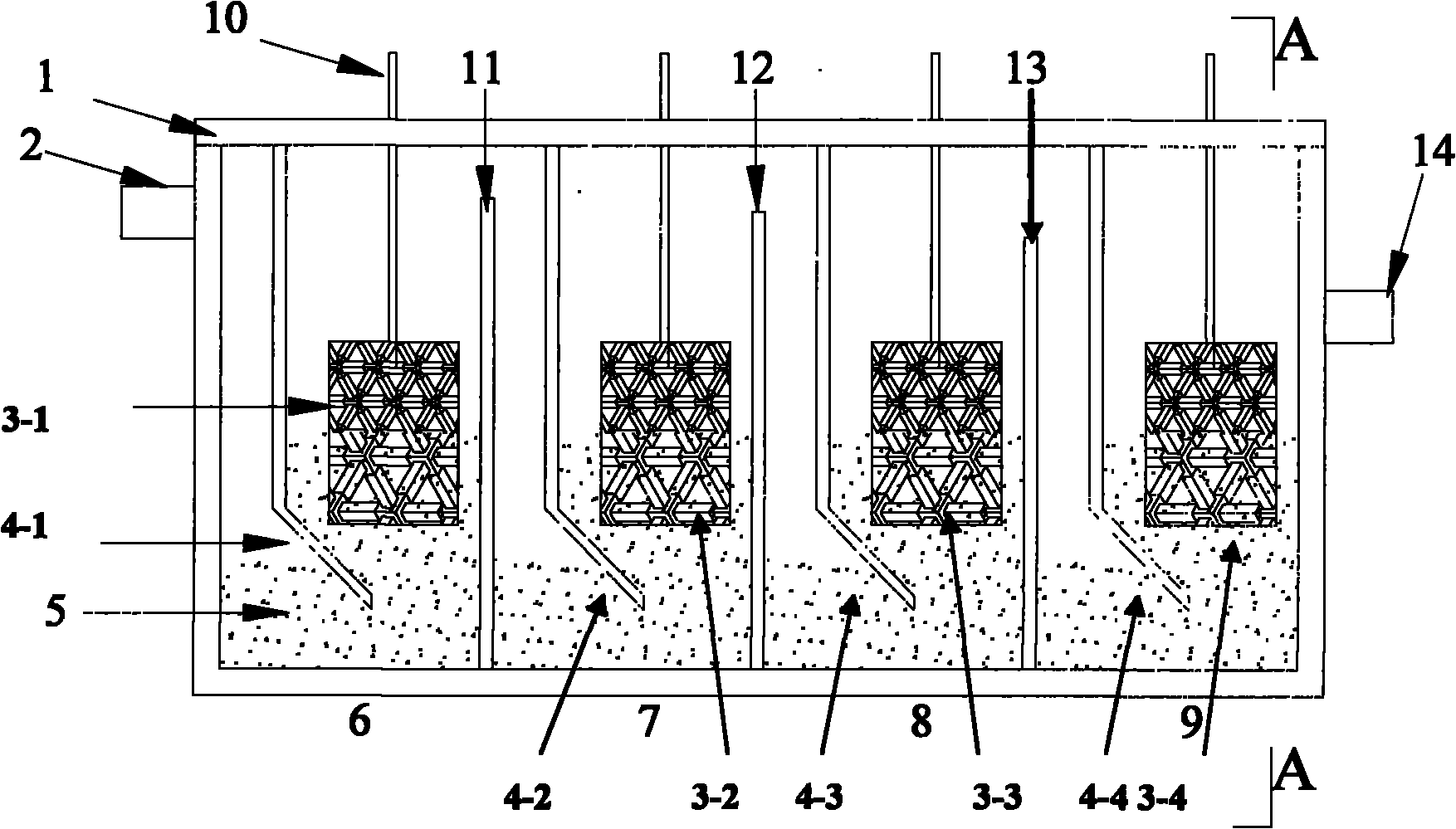
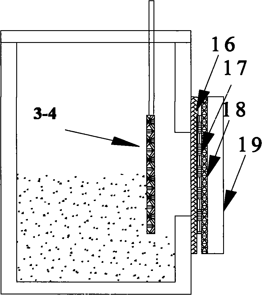
[0024] The microbial fuel cell stack is an anaerobic baffle structure, such as figure 1 and 2As shown, it includes a box body 1, three overflow plates 11, 12 and 13, four baffle plates 4-1, 4-2, 4-3 and 4-4, and four anodes 3-1 and 3-2 , 3-3 and 3-4 and four cathodes; the left and right side walls of the box 1 are respectively provided with a water inlet 2 and a water outlet 14; The side wall and the rear side wall are airtightly connected, and the box is divided into 4 connected compartments 6, 7, 8 and 9, and the volumes of the 4 compartments are equal; the height of the overflow plates 11, 12 and 13 is smaller than that of the water inlet 2 distance from th...


PUM

PropertyMeasurementUnit
angleaaaaaaaaaa
thicknessaaaaaaaaaa
particle diameteraaaaaaaaaa

Abstract

The invention discloses an anaerobic baffle plate type microbial fuel cell stack. The anaerobic baffle plate type microbial fuel cell stack comprises a tank body, at least one overflow plate, at least two baffle plates, an anode and a cathode; the left and right side walls of the tank body are provided with a water inlet and a water outlet respectively; the overflow plate divides the tank body into at least two communicated compartments; the height of the overflow plate is gradually reduced from the water inlet to the water outlet; each compartment is provided with one of the baffle plates for dividing the compartments into two communicated areas, and the area between the baffle plate and the overflow plate or the side wall of the tank body provided with the water outlet is an upstream area; the anode is arranged in the upstream area, and the anode is led out of the tank body through a lead; and the front side wall or the rear side wall of the tank body corresponding to the upstream area is provided with the cathode. The anaerobic baffle plate type microbial fuel cell stack can be used for treating high-concentration reflux sewage of a municipal sewage treatment plant and high-concentration industrial wastewater.

Description

technical field [0001] The invention relates to an anaerobic baffle type microbial fuel cell stack. Background technique [0002] Microbial fuel cell (MFC) is a device that uses microorganisms as a catalyst to directly convert the chemical energy contained in organic matter into electrical energy under anaerobic conditions. The typical structure includes an anode chamber, a cathode chamber and a proton exchange membrane. The principle of electricity generation is: During the process of microorganisms oxidizing organic matter in an anaerobic environment, the protons produced are transferred to the cathode through the diffusion of the proton exchange membrane, and the electrons are transferred to the anode through the action of mediators or cell surface enzymes, and then transferred to the cathode through an external circuit, forming current. The electrons, protons and oxygen in the cathode (or other electron acceptors) react under the action of the cathode catalyst to genera...

Claims


Application Information

Patent Timeline
Patent Type & Authority Applications(China)
IPC IPC(8): H01M8/24H01M8/16H01M8/04H01M8/04186H01M8/2455
CPCY02E70/20Y02E60/527Y02E60/50
Inventor 孔令才倪晋仁
Owner PEKING UNIV
Why Eureka
Try Eureka